Wind turbine blade holding arrangement
- Summary
- Abstract
- Description
- Claims
- Application Information
AI Technical Summary
Benefits of technology
Problems solved by technology
Method used
Image
Examples
Embodiment Construction
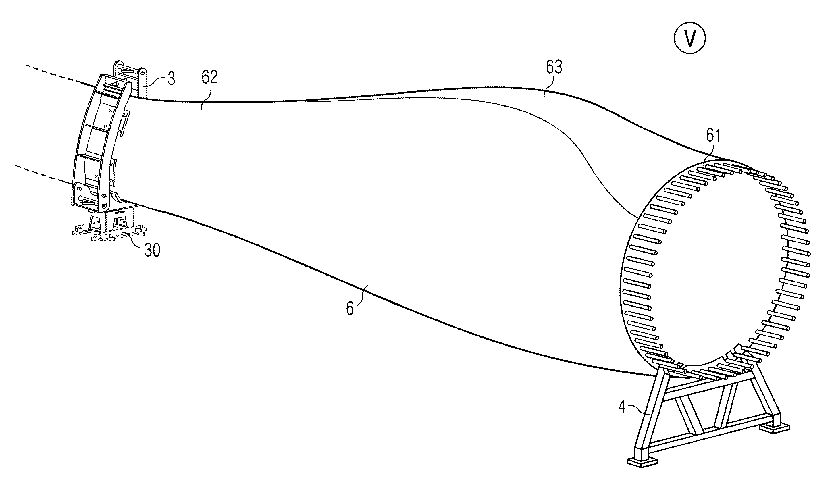
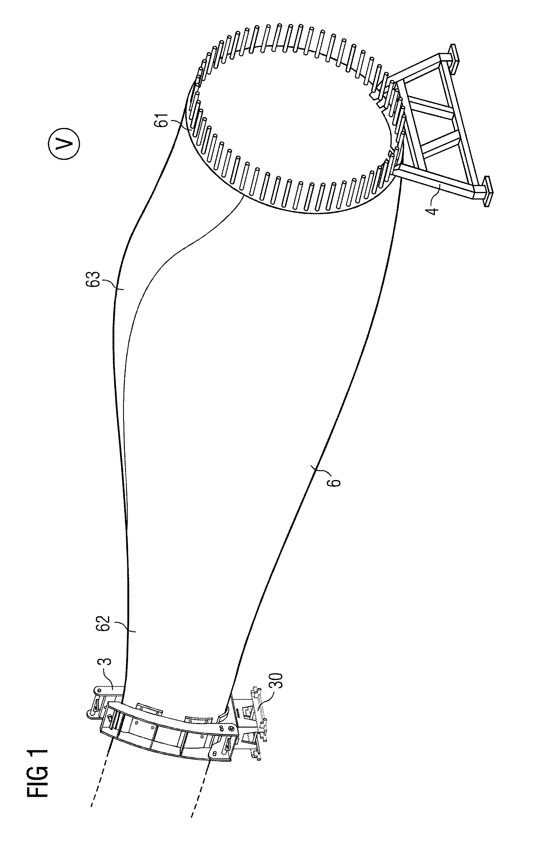
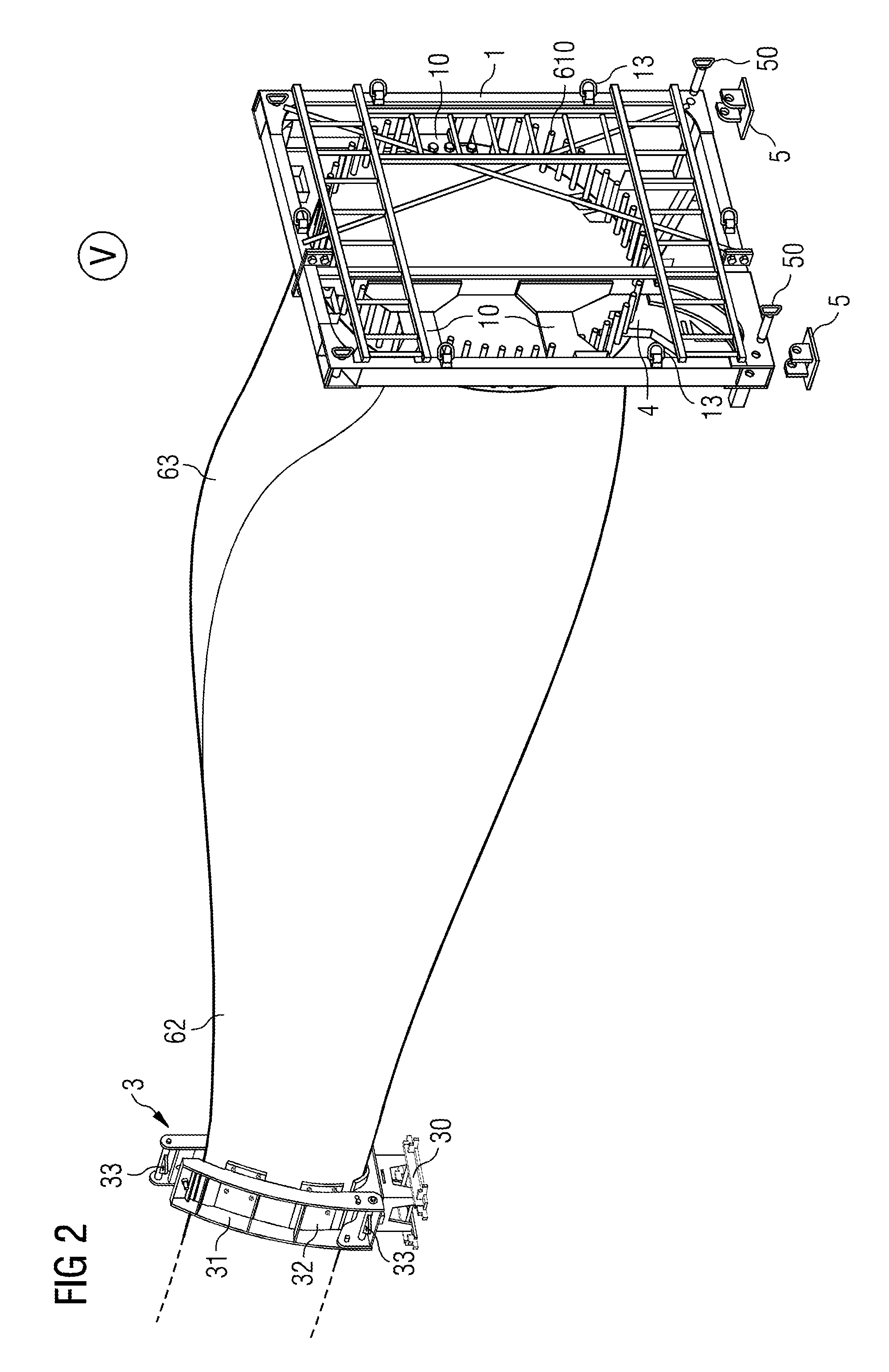
[0039]FIG. 1 shows a blade 6 in a first storage stage, supported by a root end foot 4 and a tip clamp 3 of a holding arrangement according to an embodiment. In this basic configuration, the root end 61 is being supported by the root end foot 4, and the blade's airfoil portion 62 is being supported in an airfoil clamp 3 or “tip clamp”3. This position or blade orientation may be required for a while between the manufacturing and transport phases. The root end foot 4 is secured to the root end 61 using several of the already mounted bolts 610 protruding from the root end 61, which will later be used to mount the blade 6 to the hub of a wind turbine. To this end, the root end foot 4 includes a planar portion with a number of rigid protruding tubes that are arranged to coincide with the positions of certain pinbolts 610. The planar portion of the root end foot 4 lies against a planar surface of the root end. The root end foot 4 is compact and economical, since it does not need to extend ...
PUM
| Property | Measurement | Unit |
|---|---|---|
| Angle | aaaaa | aaaaa |
| Shape | aaaaa | aaaaa |
| Width | aaaaa | aaaaa |
Abstract
Description
Claims
Application Information
 - R&D
- Intellectual Property
- Life Sciences
- Materials
- Tech Scout
- Unparalleled Data Quality
- Higher Quality Content
- 60% Fewer Hallucinations
Browse by: Latest US Patents, China's latest patents, Technical Efficacy Thesaurus, Application Domain, Technology Topic, Popular Technical Reports.
© 2025 PatSnap. All rights reserved.Legal|Privacy policy|Modern Slavery Act Transparency Statement|Sitemap|About US| Contact US: help@patsnap.com


