
Modular Tensile Vegetated Wall System

Inactive Publication Date: 2014-10-30
TOMLINSON DAVID J
View PDF0 Cites 11 Cited by
  • Summary
  • Abstract
  • Description
  • Claims
  • Application Information

AI Technical Summary

Benefits of technology

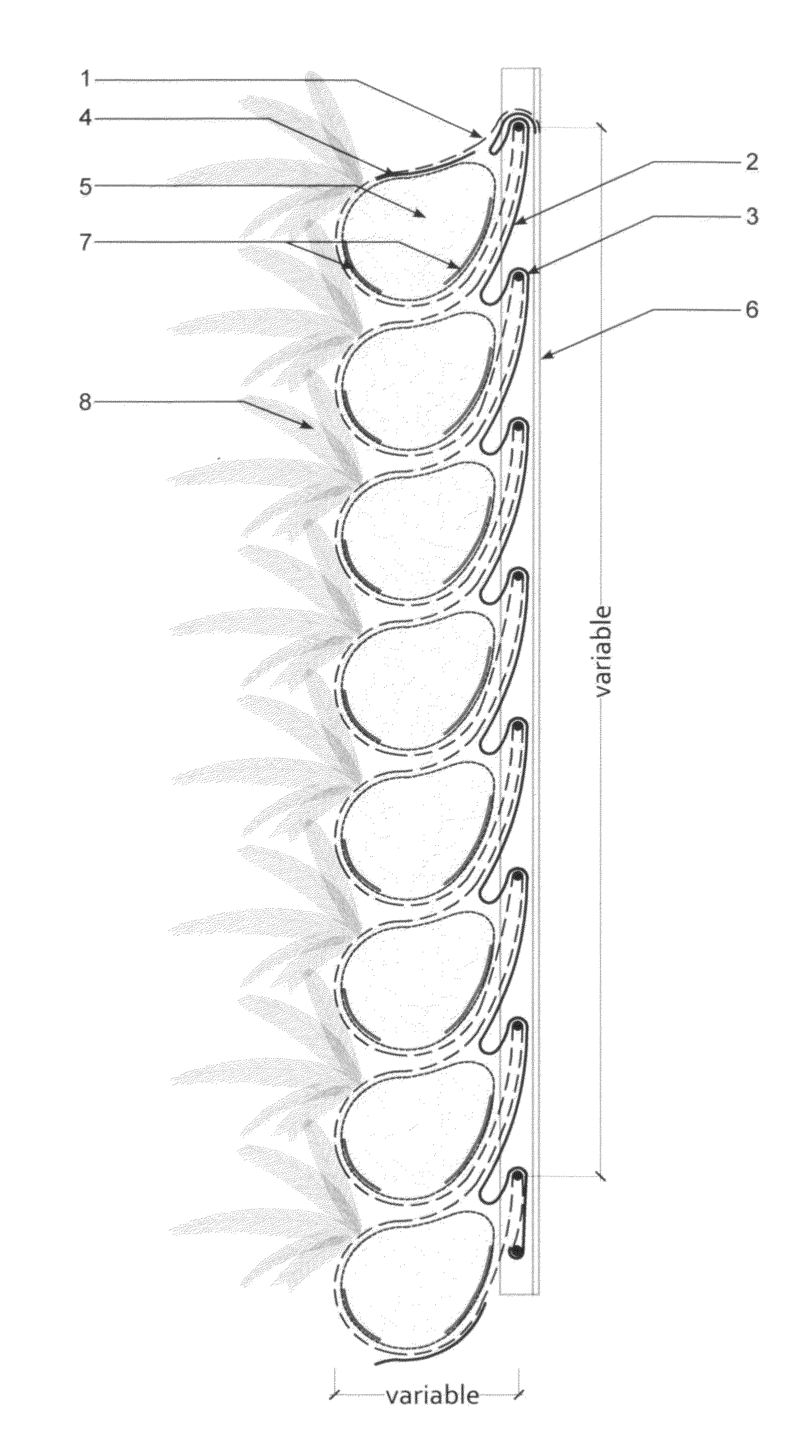
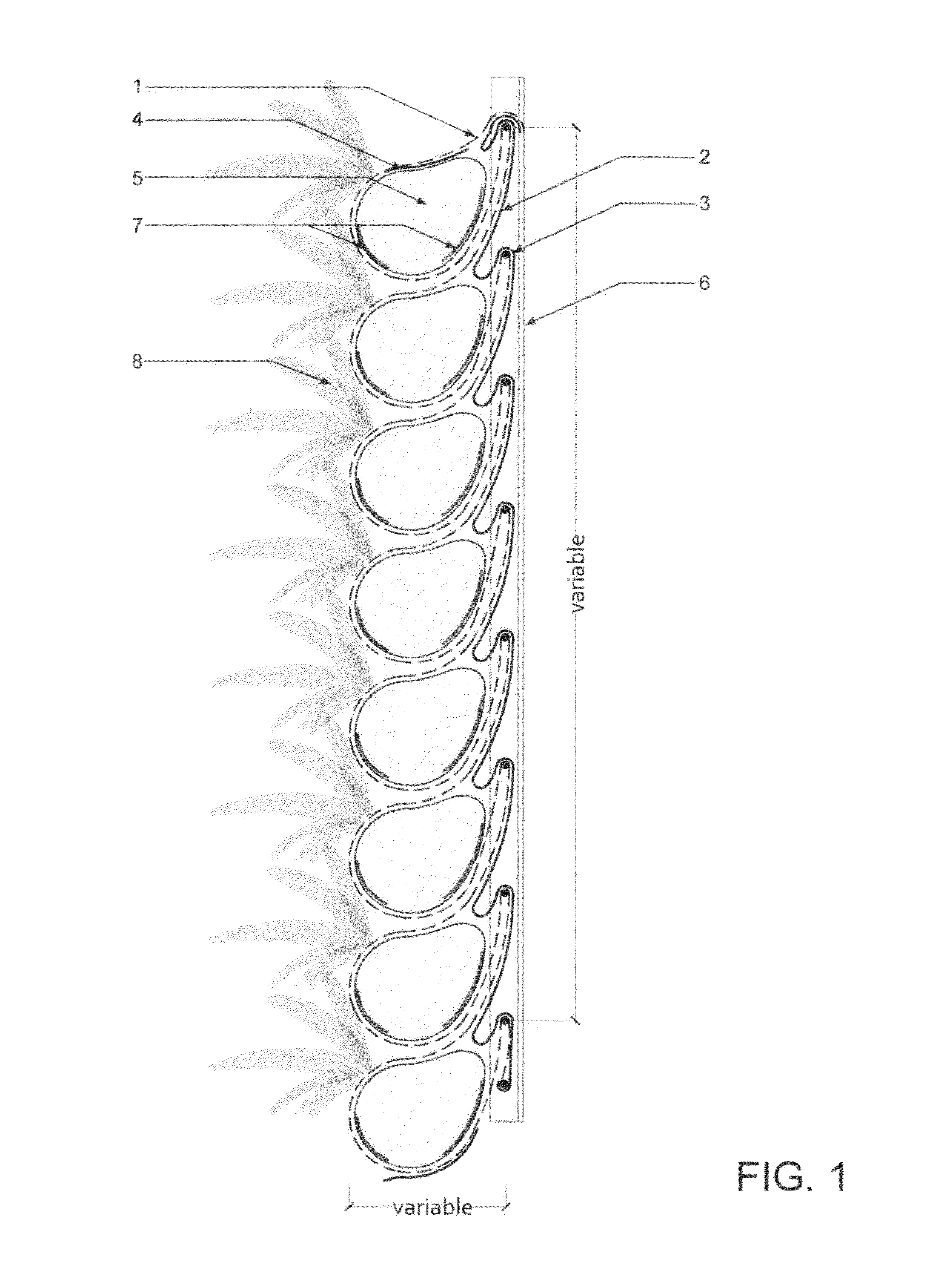
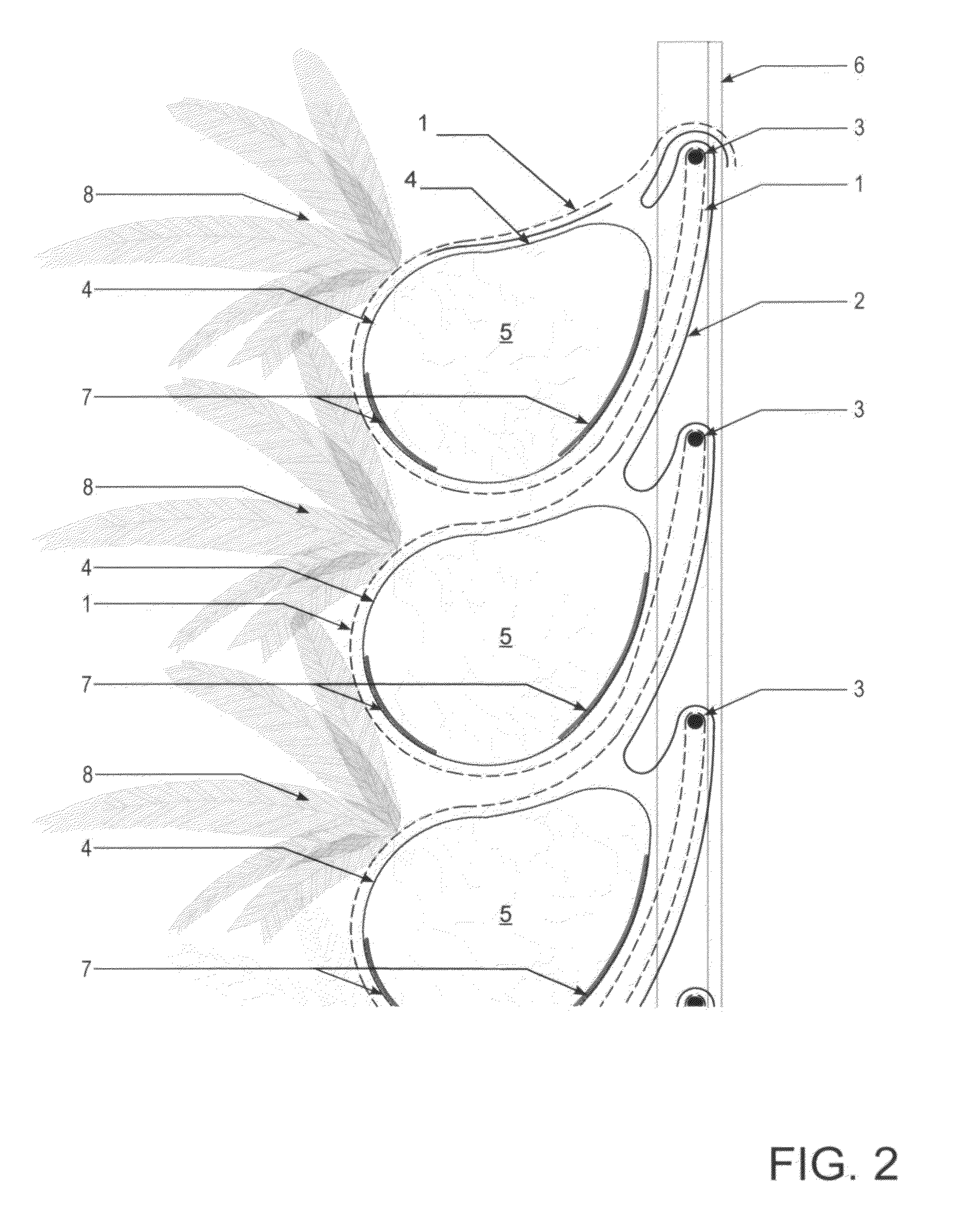
The invention is a new type of vegetated wall system that uses a lightweight tensile-based structural system instead of compressive members. By folding a continuous fabric over a modular frame, the system can increase its capacity for plant growing medium compared to other systems. The horizontal configuration also allows for increased root growth and a volume of growing medium. The invention also includes the ability to change the geometry of the folds and the modular structural frames to achieve various effects and benefits.

Problems solved by technology

However, each system has its own draw back.
Façade coverage is also more challenging to predict and control.
Green wall systems often uniform coverage but often constrict root growth due to their cellular construction.
The materiality of their cellular construction can also contribute to over-heating of plant material, resulting in either plant stress or death.
Green walls also employ a large amount of material to support the vegetation, increasing their carbon footprint and embodied energy.
While well adapted to a harsh growing environment such as a building façade, non-native species do not necessarily provide ecological functions such as habitat provision.
Likewise, green walls and vertical gardens deprive the plants of their main strategy for stress management: a microbial-rich soil environment.
This requires costly irrigation systems that must supply all the prerequisite nutrients to the plant, as they are unable to synthesize many of these nutrients in natural fashion, or in combination with microbial processes.
This in turn results in an extremely delicate, un-resilient system.

Method used


Image

  • Modular Tensile Vegetated Wall System
  • Modular Tensile Vegetated Wall System
  • Modular Tensile Vegetated Wall System

Examples


Embodiment Construction

[0034]A modular tensile vegetated wall system as provided by the embodiments represented in the accompanying drawings which form a part hereof and are referenced below.

[0035]In many embodiments, the invention is bi-laterally symmetrical about a vertical axis, and a feature on one side or along one edge is generally replicated on the opposite side. This is evident in the drawings and a call out for one item on one side presumes the presence of the item on the opposite side where the drawing depicts a bi-laterally symmetrical condition. Elements in an illustration of an embodiment may be omitted for clarity from another illustration of the same or different embodiment. It will become clear to one skilled in the art that the invention is not limited to a single preferred embodiment, but that different configurations of the elements described herein and based on the understanding of the invention will enable one to address various external parameters within the system of the invention p...


PUM


Abstract

Embodiments include but are not limited to modular tensile vegetated wall systems. A module may be comprised of a modular structural frame consisting of not less than two parallel vertically oriented structural members supporting at least one transverse support, wherein a first continuous fabric is folded horizontally over the modular structural frame such that the volume of the folds may be sufficient to contain both plant material and growing medium on the ventral side, and wherein the first continuous fabric has at least one opening to receive planting material, and wherein a second continuous fabric is folded horizontally over the modular structural frame on the dorsal side and partially folded into the cavity or cavities produced by the fold or folds of the first fabric. The vegetated wall system includes integrated irrigation. Other embodiments may be described and / or claimed.

Description

RELATED US APPLICATION DATA[0001]The present application claims priority to U.S. Provisional Patent Application No. 61 / 638,453, filed Apr. 25, 2012, the entire specification of which is hereby incorporated by reference in its entirety for all purposes.PUBLICATION CLASSIFICATION[0002]47 / 65.8;TECHNICAL FIELD[0003]The invention relates to a system for growing plants. More specifically, the invention relates to a system for growing plants along or adjacent to a vertical or inclined wall. Embodiments of the present invention relate generally to a vegetated wall system and more particularly to a modular tensile vegetated wall system.BACKGROUND OF THE INVENTION[0004]Vegetated wall systems of various types are becoming more widely known. Such systems are typically deployed to provide one or more ecosystem services in urban areas, such as: (i) habitat provision; (ii) ambient green space; (iii) noise attenuation; (iv) thermal regulation; and (v) air filtration, which may benefit the urban env...

Claims


Application Information

Patent Timeline
IPC IPC(8): A01G9/02
CPCA01G9/025Y02P60/20
Inventor TOMLINSON, DAVID, J.
Owner TOMLINSON DAVID J
Learn More