Pressure indication device of inflation machine with safety pressure relief

Active Publication Date: 2014-10-30
ANHUI FUYANG FENGJINBA MASCH & ELECTRIC CO LTD
View PDF21 Cites 10 Cited by
  • Summary
  • Abstract
  • Description
  • Claims
  • Application Information

AI Technical Summary

Benefits of technology

[0010]Another objective of the present invention is to provide a pressure indication device of inflation machine. The pressure indication device is connected to an inflation mechanism of an inflation machine. The inflation mechanism comprises an air compartment formed on a piston cylinder. The air compartment is provided with at least two outlet openings that are respectively coupled to a first conveyance tube and a second conveyance tube, wherein the first conveya

Problems solved by technology

Consequently, there is no need to adopt the conventional pressure gauge th

Method used


Image

  • Pressure indication device of inflation machine with safety pressure relief
  • Pressure indication device of inflation machine with safety pressure relief
  • Pressure indication device of inflation machine with safety pressure relief

Examples


Example

[0019]The following descriptions are exemplary embodiments only, and are not intended to limit the scope, applicability or configuration of the invention in any way. Rather, the following description provides a convenient illustration for implementing exemplary embodiments of the invention. Various changes to the described embodiments may be made in the function and arrangement of the elements described without departing from the scope of the invention as set forth in the appended claims.

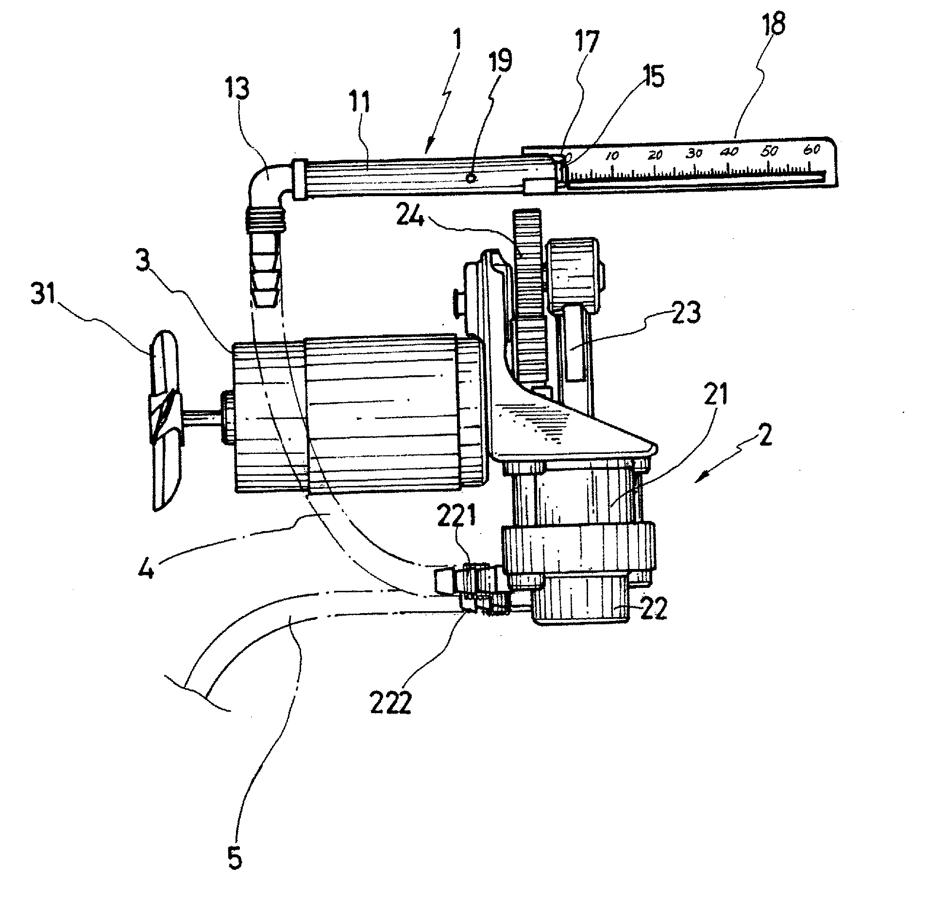
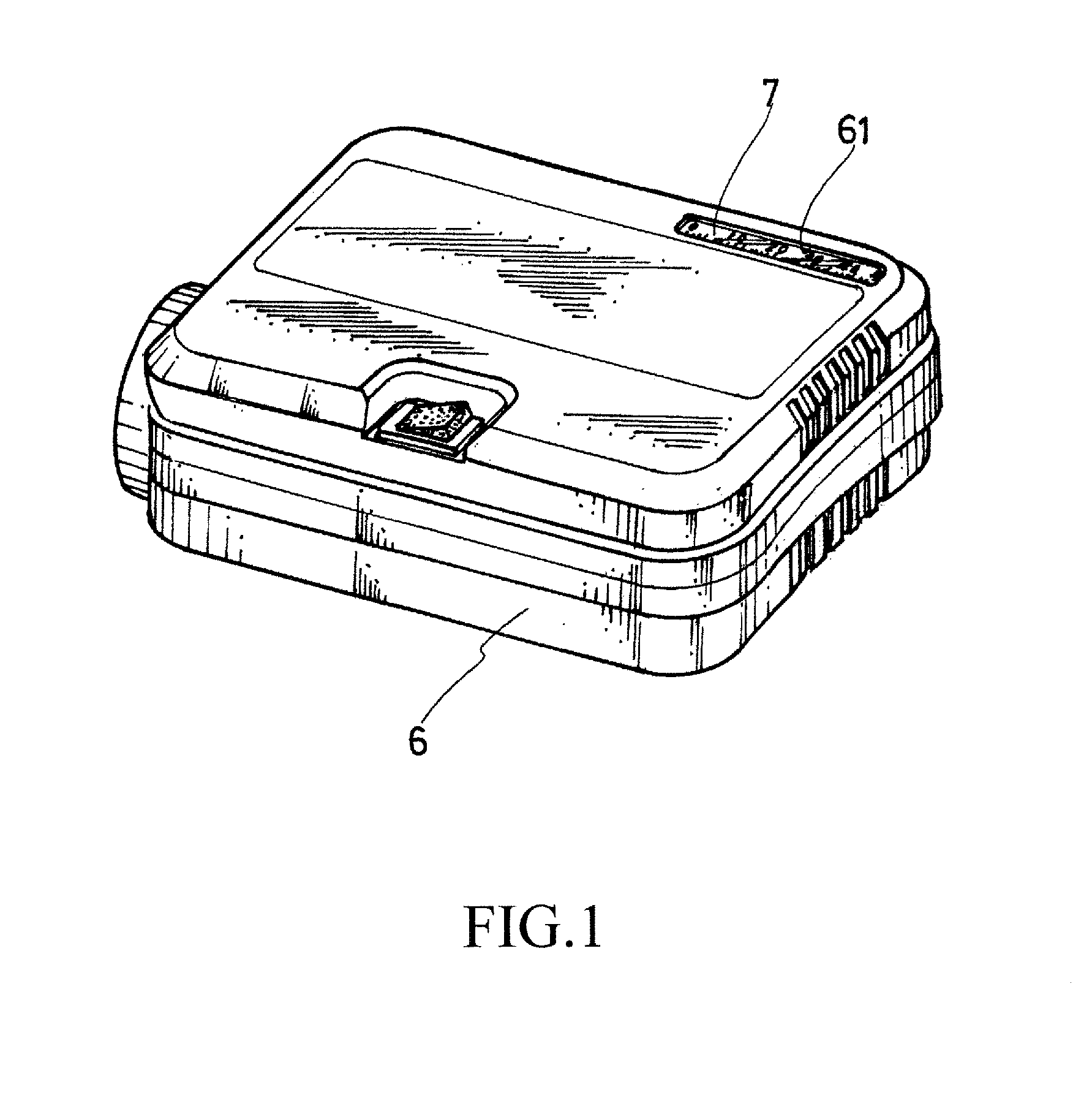
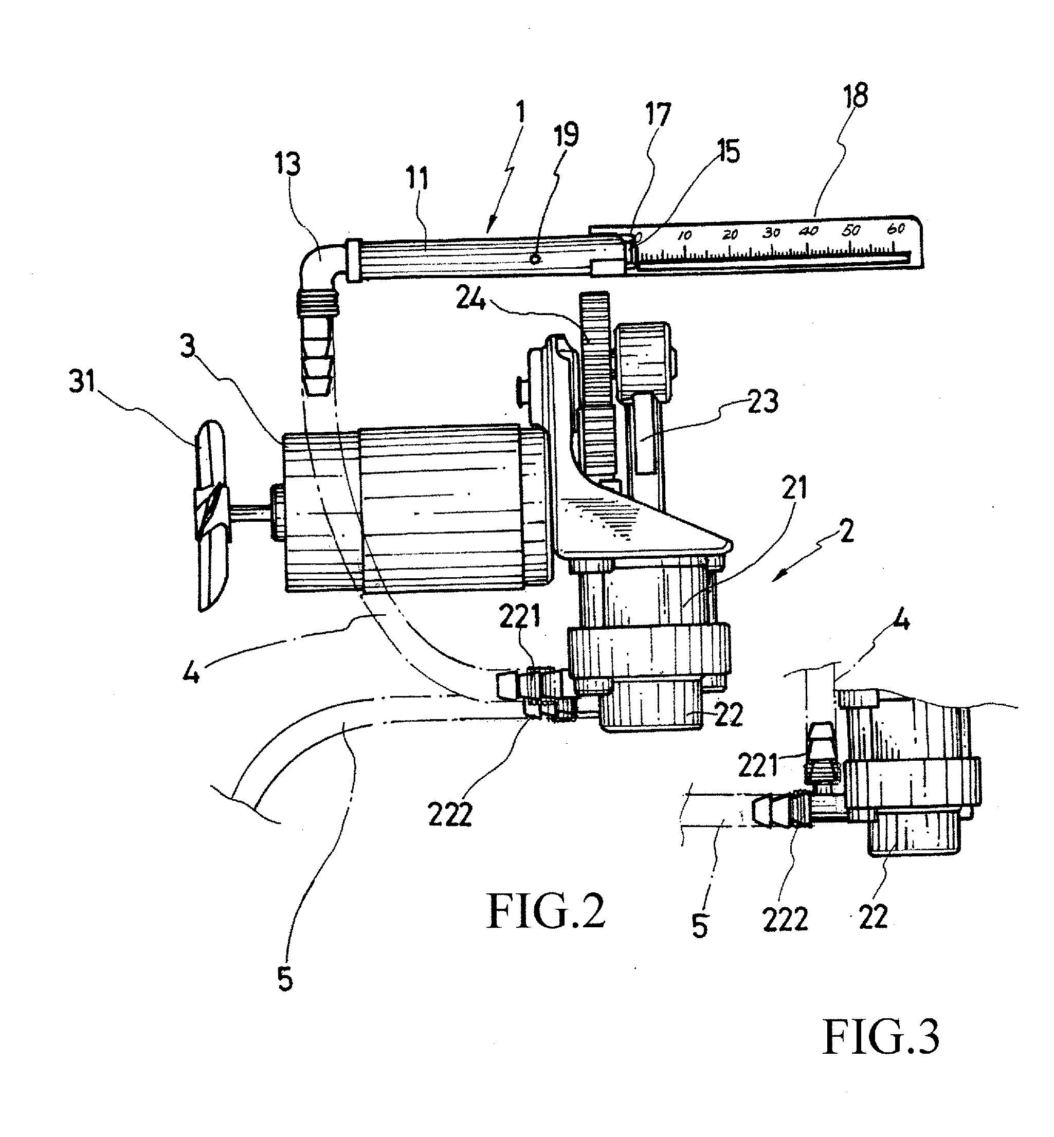
[0020]Referring to FIGS. 1, 2, 3, 4, and 5, the present invention discloses a pressure indication device of inflation machine. The pressure indication device 1 is mounted to an inflation machine 6. The pressure indication device 1 comprises a hollow tubular body 11. The hollow tubular body 11 has two ends that are respectively provided with a protection cover 12 and an inlet joint 13. The protection cover 12 forms a through hole 121. The inlet joint 13 forms an inlet opening 131 extending outside th...


PUM


Abstract

A pressure indication device is provided to connect to an inflation mechanism of an inflation machine. The pressure indication device includes a hollow tubular body in which a push bock is received in a manner of being movable by a pressure conducted into the hollow tubular body and connected to a linearly movable plate and biased by an elastic element. The hollow tubular body has a tubular wall forming a pressure relief hole at a preset position corresponding to a maximum allowable pressure level. A scale bar having graduations is provided along a moving path of the plate. The elastic force of compression of the elastic element serves as a reaction force (restoration and returning force) for the linear movement of the plate. A pressure conducted into the hollow tubular body from the inflation machine drives the plate to move and thus indicates the pressure level.

Description

TECHNICAL FIELD OF THE INVENTION[0001]The present invention generally relates to a pressure indication device of inflation machine, and more particularly to an inflation machine that comprises an inflation mechanism having an air compartment that is provided with at least two outlet openings respectively coupled to first and second conveyance tubes, of which the first conveyance tube is connected to the pressure indication device and the second conveyance tube supplies air to an object to be inflated, and the pressure indication device comprises an elastic element of which an elastic force of compression is used to serve as a reaction force (restoration returning force) for linear movement of a plate and correspondingly, a pressure induced in the air compartment drives the plate to make a linear movement of which the distance of movement is indicative of the level of pressure, wherein when the inflation pressure exceeds the maximum pressure setting, the excess of the inflation press...

Claims


Application Information

Patent Timeline
IPC IPC(8): G01L7/04
CPCG01L7/043G01L7/166G01L17/00G01L19/0618G01L19/10
Inventor CHEN, CHI-WEN
Owner ANHUI FUYANG FENGJINBA MASCH & ELECTRIC CO LTD
Why Eureka
Try Eureka