Burner assembly for cooking equipments

Inactive Publication Date: 2014-10-30
WHIRPOOL SA
View PDF4 Cites 17 Cited by
  • Summary
  • Abstract
  • Description
  • Claims
  • Application Information

AI Technical Summary

Benefits of technology

[0009]In view of the foregoing, it is an objective of the present invention to provide a burner assembly for cooking eq

Problems solved by technology

In the current state of the art, there is often only one of flame output ring, which limits the thermal efficiency of the burner since it does not allow the distribution of the flames under the entire surface of the cooking utensil.
Note, however, that this type of burner provides a significantly complex constructive aspect of rustic appearance which requires that for each flame output ring, there is an independent mixing chamber.
This configuration shows a burner of construction and complex mounting and therefore costly that, moreover, also requires the manufacture and mounting of two individual covers of fittings at specific locations of the piece.
The document BR PI0112498 provides a construction in which a burner provided with two crowns of porticos have a single mixing chambe

Method used


Image

  • Burner assembly for cooking equipments
  • Burner assembly for cooking equipments
  • Burner assembly for cooking equipments

Examples


Embodiment Construction

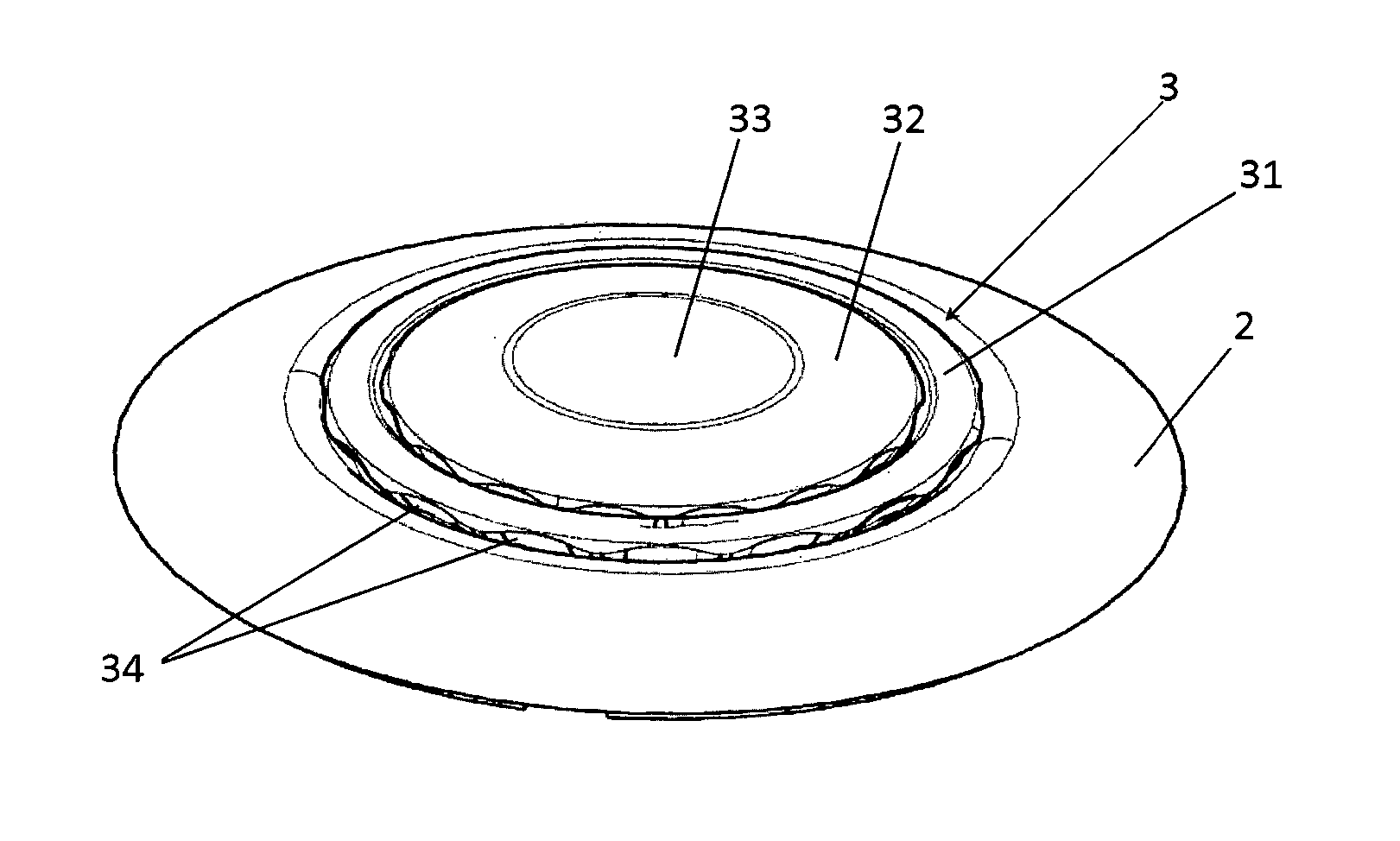
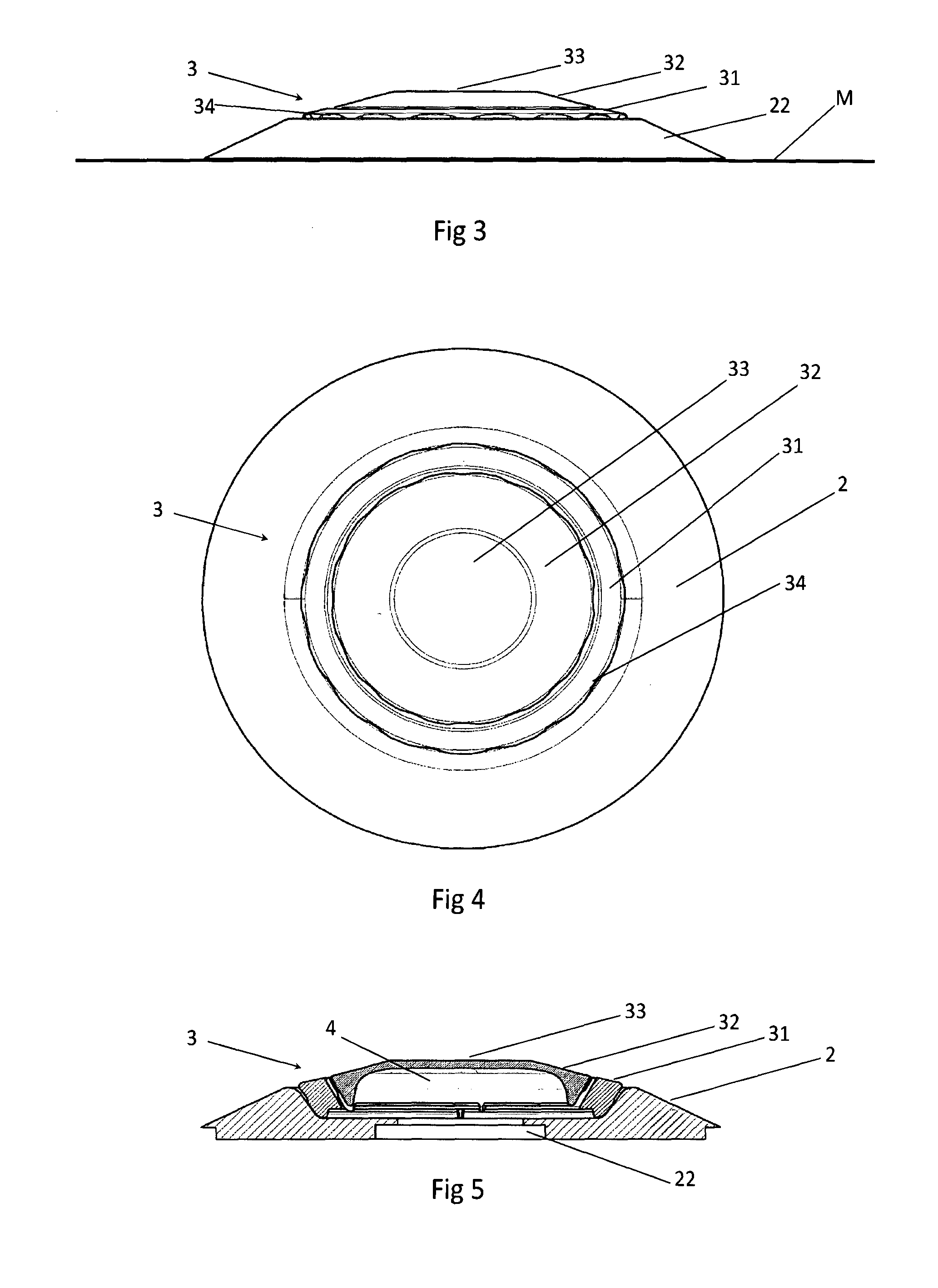
[0030]The accompanying FIG. 1 shows a general view of burner assembly constructed according to a preferred embodiment of the present invention allowing visualization of the base 2 which, in general, rests on the cooking table M which may also have lower prolongations (not shown) for connection to the internal components for interconnection with the supply source of gas and air.

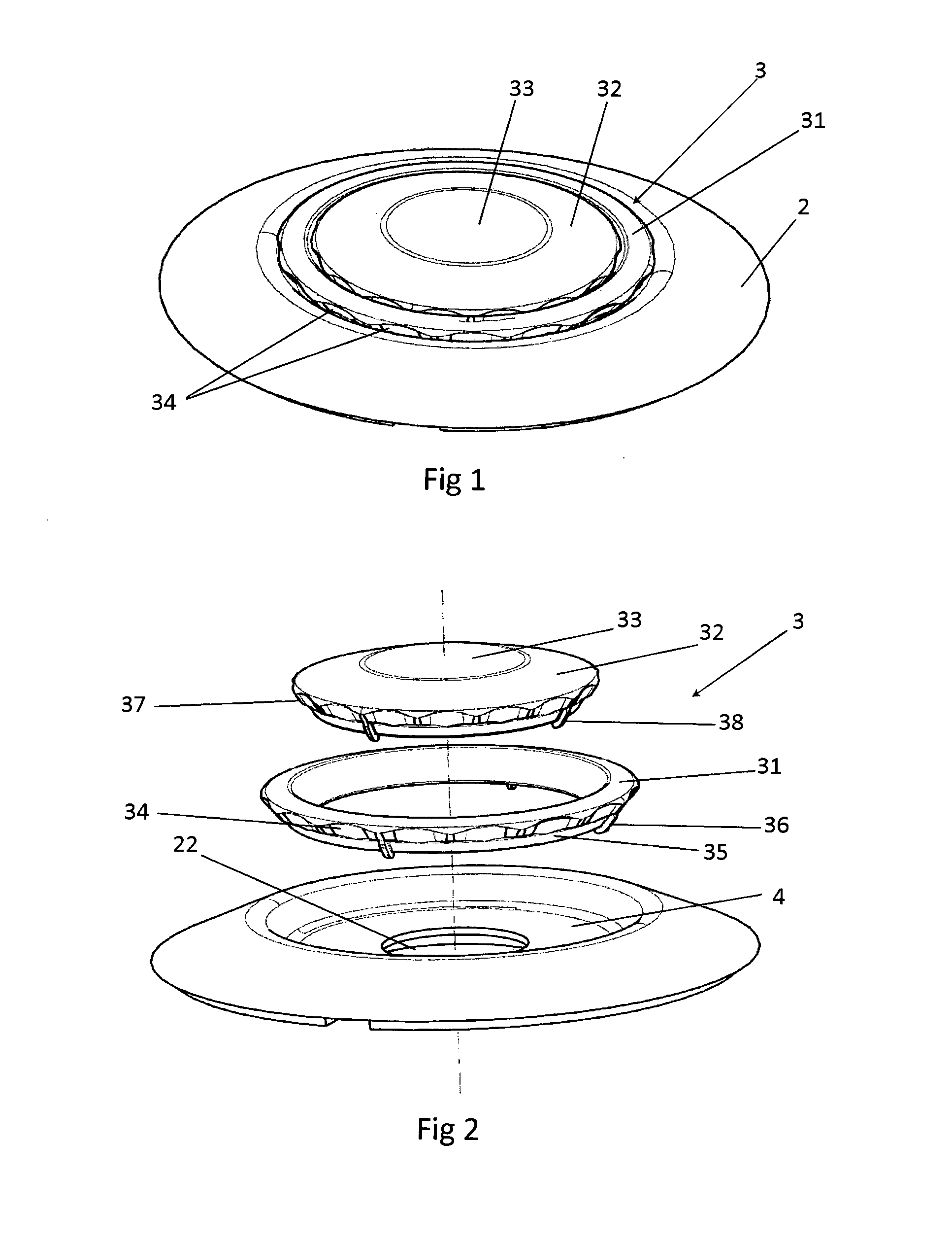
[0031]In the embodiment shown—which, it should be noted, is illustrative and not restrictive, since the piece can present other aesthetic configurations without thereby escaping from the scope of protection claimed in the present application—the base 2 has a substantially frustoconical format comprising, in its internal region, a central orifice 22 for the coupling of system for feeding air-fuel mixture (not shown).

[0032]A spreading cover 3—better shown in FIG. 2—is, in the exemplary embodiment shown in the appended figures, consisting of a perimeter ring 31 to the center from which it couples a disc 32 with p...


PUM


Abstract

The present invention relates to a burner assembly for cooking equipments that has been designed to provide significant improvement in thermal efficiency of the burner and making easier the cleaning process by the user. The burner assembly comprises a base (2) upon which a spreading cover (3) rests, and wherein the coupling of the spreading cover (3) on the base (2) originates one internal chamber of expansion (4) of air-fuel mixture which is released through porticos existing under the perimeter edge of the spreading cover (3), and wherein the base (2) comprises in its internal region at least one feeding orifice (22); the spreading cover (3) comprises at least one perimeter ring (31) cooperating with the base (2) and at least one disc (32) cooperating with the perimeter ring (31) and the burner assembly (1) comprises at least one internal chamber of mixture (4) cooperating with the porticos of the spreading cover (3).

Description

FIELD OF THE INVENTION[0001]The present invention relates to a burner assembly for cooking equipments, and more specifically to a burner provided with a spreading cover having two or more portico rings to output air-fuel mixture, which was developed to provide significant improvement in thermal efficiency and heat power of the equipment, in addition to presenting smooth geometry (both in the base and in the spreading cover) providing greater easiness of cleaning by the user, and which can also provide a simpler and more economical constructive process than similar known ones.BACKGROUND OF THE INVENTION[0002]As is well known, the burners are components of stoves that are located close to the cooking table and comprise the elements responsible for receiving the fuel from the supply source (whether it a cylinder of liquefied petroleum gas or a public network of natural gas), mix it to ambient air and release the fuel-air mixture to burn, when requested by the user.[0003]As it regards m...

Claims


Application Information

Patent Timeline
IPC IPC(8): F24C3/08F23D14/06F23D14/34
CPCF24C3/08F23D14/06F23D14/34F23D14/065F23D14/08F23D14/085F23D2900/14062
Inventor SILVA, MARCOS RAPHAEL DAFAVERI, RODRIGO FREGUILIA DE
Owner WHIRPOOL SA
Why Eureka
Try Eureka