Current Sensing Circuit Disconnect Device and Method

a current sensing circuit and disconnect device technology, applied in the direction of emergency power supply arrangements, transportation and packaging, electric vehicles, etc., can solve the problems of wasting electricity and the valuable resources used to generate, unnecessarily waisting power, and wasting billions of kw hours of battery charging devices running in standby and idle modes

Inactive Publication Date: 2014-10-30
SCHWARTZ ROBERT M
View PDF12 Cites 5 Cited by
  • Summary
  • Abstract
  • Description
  • Claims
  • Application Information

AI Technical Summary

Benefits of technology

[0011]It is accordingly an object of the present invention to provide a battery charging device that will disconnect or mechanically brea

Problems solved by technology

In particular the use of energy by devices standing in idle mode or standby mode has been criticized as using electricity to no purpose, and thus wasting electricity and the valuable resources used to generate it.
As a result the load draws no current from the charging circuit on the secondary side of the charg

Method used


Image

  • Current Sensing Circuit Disconnect Device and Method
  • Current Sensing Circuit Disconnect Device and Method
  • Current Sensing Circuit Disconnect Device and Method

Examples


Embodiment Construction

:

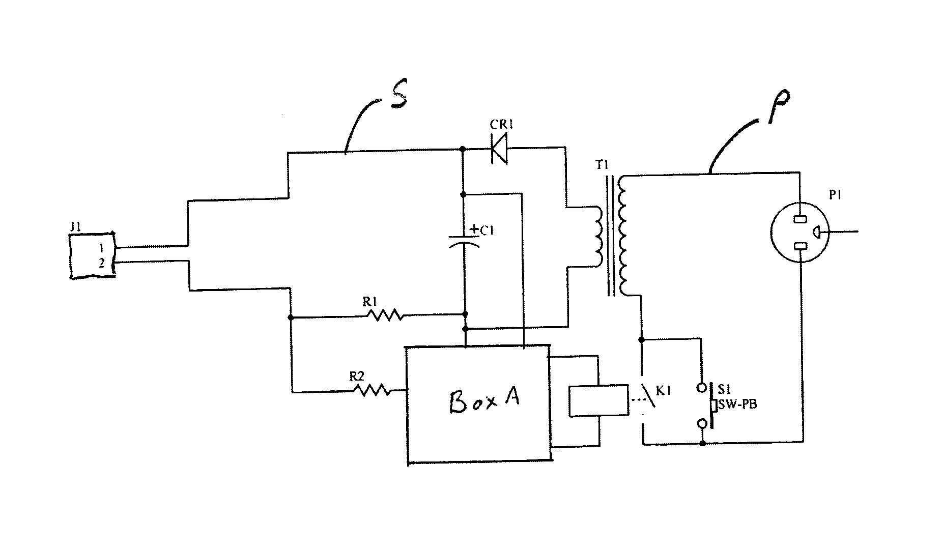
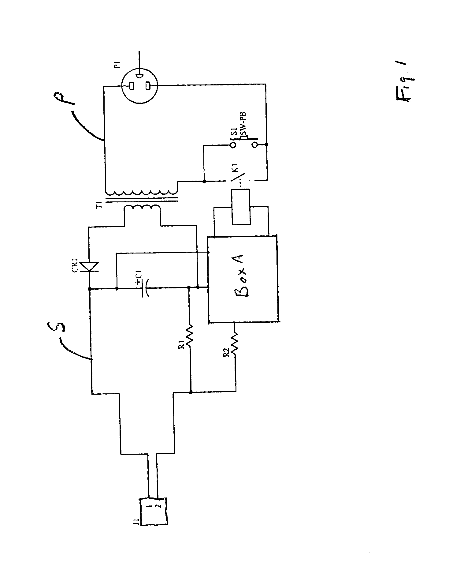
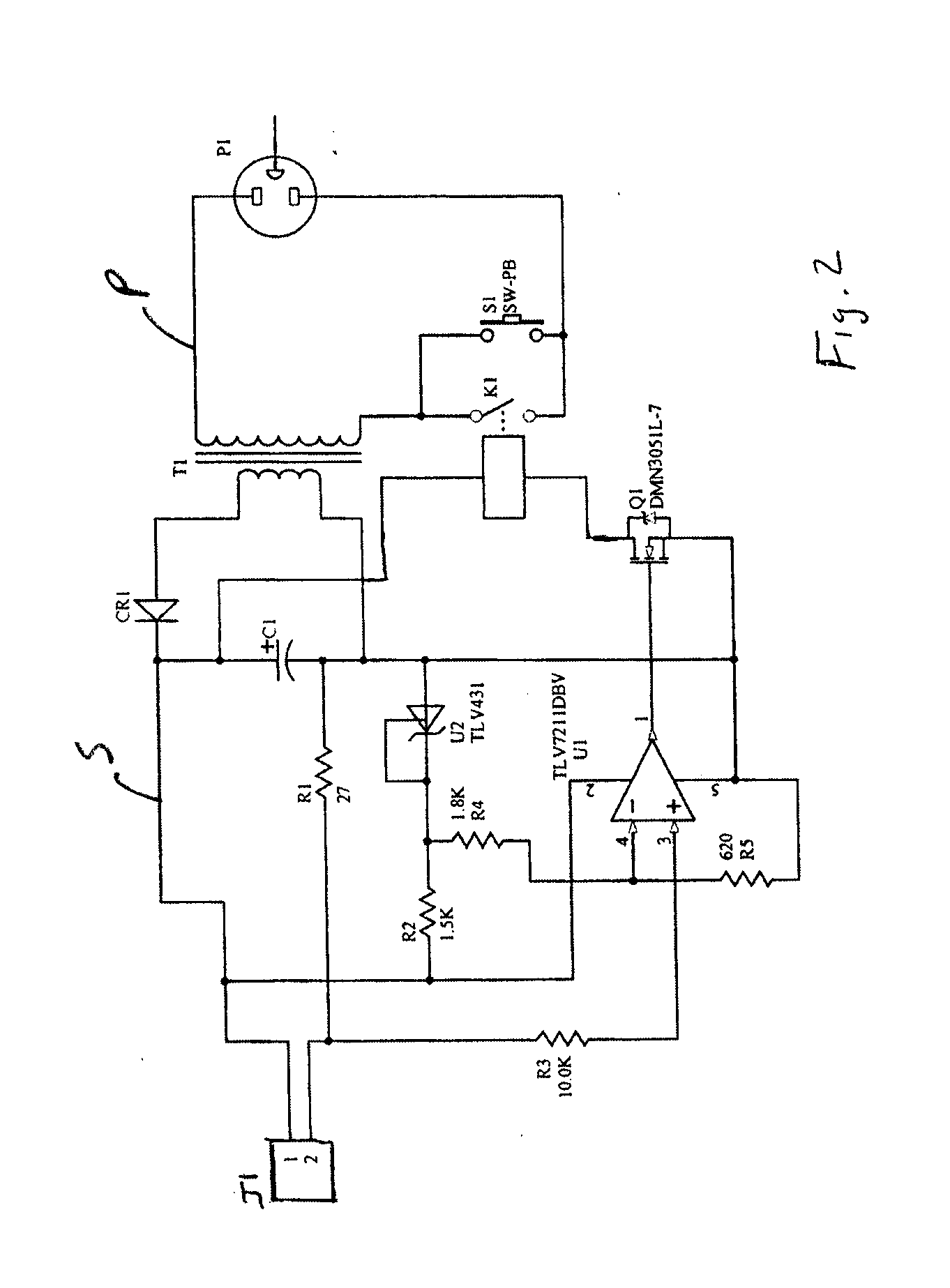
[0031]Referring now to FIG. 2, as disclosed in this application is a circuit similar to earlier circuits but more robust. CR1 represents a diode bridge to output direct current. The secondary circuit operates on a stepped down voltage from the input voltage on the primary circuit P, as a result of transformer T1. Transformer T1 can also be a switching transformer where there would be a primary circuit P and a secondary circuit S.

[0032]With a load or device to be charged connected to Jack J1 and the primary circuit switch k1 open, a user will need to activate the charging device by pressing switch S1. When current passes through the primary circuit P, a voltage will develop across resistor R1, which is a current sensing resistor of known value. Referring to comparator U1, when the pin 3 voltage is greater than the pin 4 voltage then the output of pin 1 goes high to 8 or 9 volts (in this example, the charger is a 9 volt charger) and this turns low voltage gate, mosfet semiconductor Q...


PUM


Abstract

A device and method are provided for saving power and electricity in a charging device including external power supplies and battery chargers having a primary circuit and a secondary circuit where a switch is located in the primary circuit and a current sensing device in the secondary circuit to sense when there is a drop in current in the secondary circuit or no current in the secondary circuit because the load such as a cell phone or tablet is charged and when this occurs the switch in the primary circuit is opened and the primary circuit no longer draws power from the source of power until the switch in the primary circuit is closed by either a user activating a switch to reenergize the charging device, where the switch may be powered by an on-board battery to close the primary circuit, or where a control circuit is activated by a program in the load or device to be charged, such that the charging device will cycle on and off according to an external app program residing on the device to be charged or some other device not attached to the controller.

Description

CROSS-REFERENCE TO RELATED APPLICATIONS:[0001]This application is a Continuation-in Part-application of co-pending U.S. patent application Ser. No. 13 / 908,217 filed Jun. 3, 2013, and the Continuation-in Part-application of co-pending U.S. patent application Ser. No. 13 / 892,509 filed May 13, 2013, entitled Current Sensing Circuit Disconnect Device and Method, which is a Continuation-in-Part of co-pending U.S. patent application Ser. No. 12 / 843,151 filed Jul. 26, 2010, entitled Current Sensing Circuit Disconnect Device and Method, which claims priority from U.S. Provisional Application No. 61 / 228,213 filed on Jul. 24, 2009. This application further claims priority to U.S. Provisional Application Ser. No. 61 / 825,164 filed on May 20, 2013 entitled Current Sensing Circuit Disconnect Adaptor, and U.S. Provisional Application Ser. No. 61 / 845,179 filed on Jul. 11, 2013 entitled Current Sensing Circuit Disconnect[0002]Adaptor the disclosures of each of these applications being incorporated h...

Claims


Application Information

Patent Timeline
IPC IPC(8): H02J7/00
CPCH02J7/0042H02J7/0052H02J7/00H02J9/005H02J9/007H02J2207/20
Inventor SCHWARTZ, ROBERT M.HOCKMAN, PETER M.CONNARY, GREGG M.BERKOWITZ, RICHARD A.
Owner SCHWARTZ ROBERT M
Why Eureka
Try Eureka