Antenna apparatus and communication apparatus

a technology of communication apparatus and antenna, applied in the direction of loop antenna with ferromagnetic core, instrument, radiating element structure, etc., can solve the problems of poor efficiency for receiving magnetic field, difficult to install structure inside a portable telephone having a comparatively thin size, etc., to achieve efficient draw magnetic flux, good communication characteristic, thin casing of electronic apparatus

Inactive Publication Date: 2014-10-30
DEXERIALS CORP
View PDF3 Cites 5 Cited by
  • Summary
  • Abstract
  • Description
  • Claims
  • Application Information

AI Technical Summary

Benefits of technology

[0014]Accordingly, one or more embodiments of the present invention provide a communication apparatus which, while maintaining a communication characteristic, it may be possible to downsize a casing of an electronic apparatus when assembled into the electronic apparatus.
[0017]In one or more embodiments of the present invention, in the inserting direction in which the magnetic sheet is inserted into the center portion of the antenna coil, because the two ends of the magnetic sheet are located at positions closer to the center portion than the two ends of the antenna coil so as to efficiently draw a magnetic flux to the center portion of the antenna coil, it may be possible to downsize and to make a thin casing of an electronic apparatus, while maintaining good communication characteristic, when the communication device is assembled into the electronic apparatus.

Problems solved by technology

For this reason, in the case of an antenna using the normal loop coil, its efficiency for receiving a magnetic field becomes poor.
Therefore, this structure is difficult to be installed inside a portable telephone having a comparatively thin size.
Moreover, in the case when this antenna module is assembled on the rear side of a liquid crystal display installed on a folding portable telephone, because of the thinness, it is difficult that the antenna structure disclosed in Patent Document 1 secures the space.

Method used


Image

  • Antenna apparatus and communication apparatus
  • Antenna apparatus and communication apparatus
  • Antenna apparatus and communication apparatus

Examples


Embodiment Construction

[0025]In embodiments of the invention, numerous specific details are set forth in order to provide a more thorough understanding of the invention. However, it will be apparent to one with ordinary skill in the art that the invention may be practiced without these specific details. In other instances, well-known features have not been described in detail to avoid obscuring the invention. Referring to Figures, the following description will discuss embodiments for carrying out one or more embodiments of the present invention in detail. Additionally, one or more embodiments of the present invention is not intended to be limited by the following embodiments, and various modifications may be made therein without departing from the scope of one or more embodiments of the present invention.

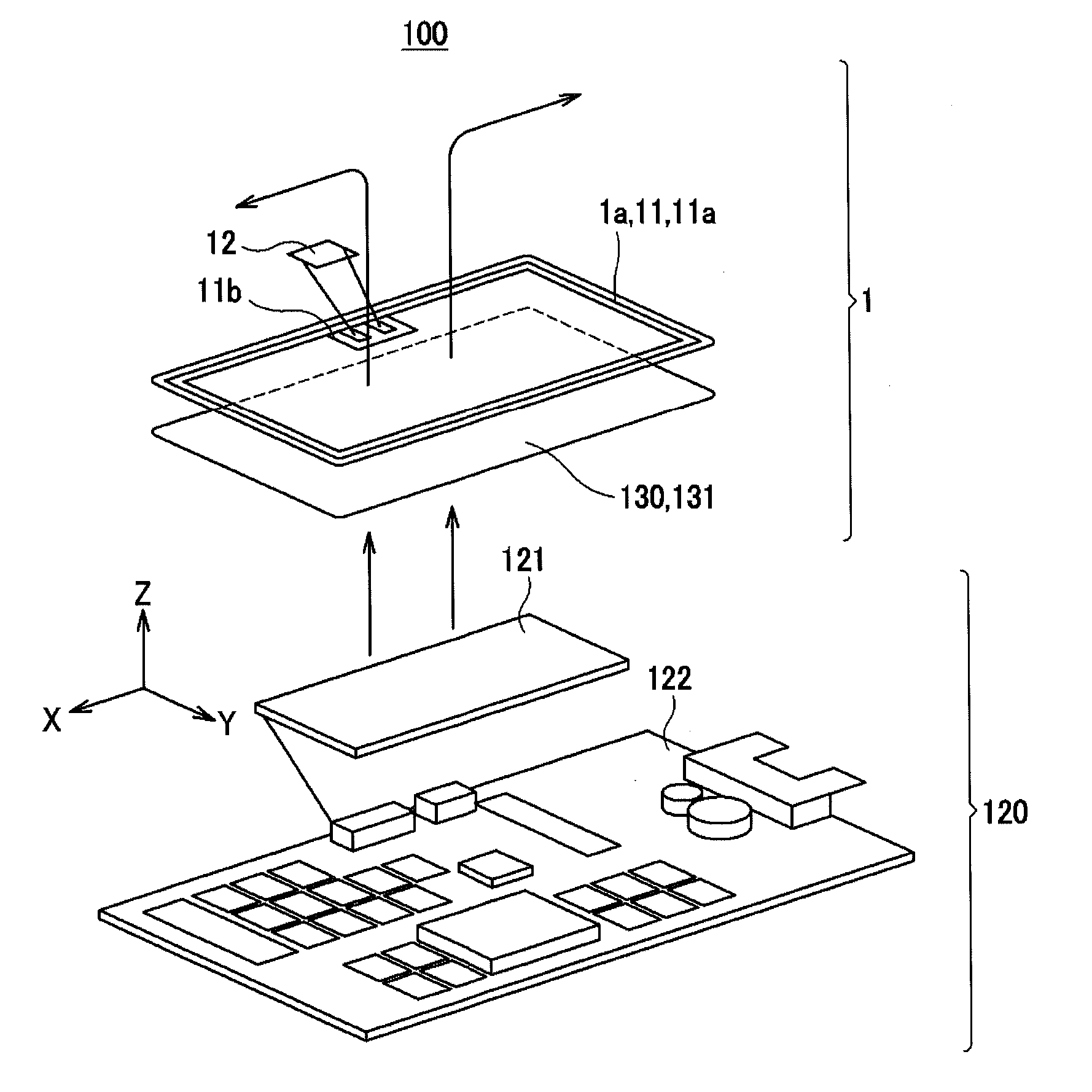
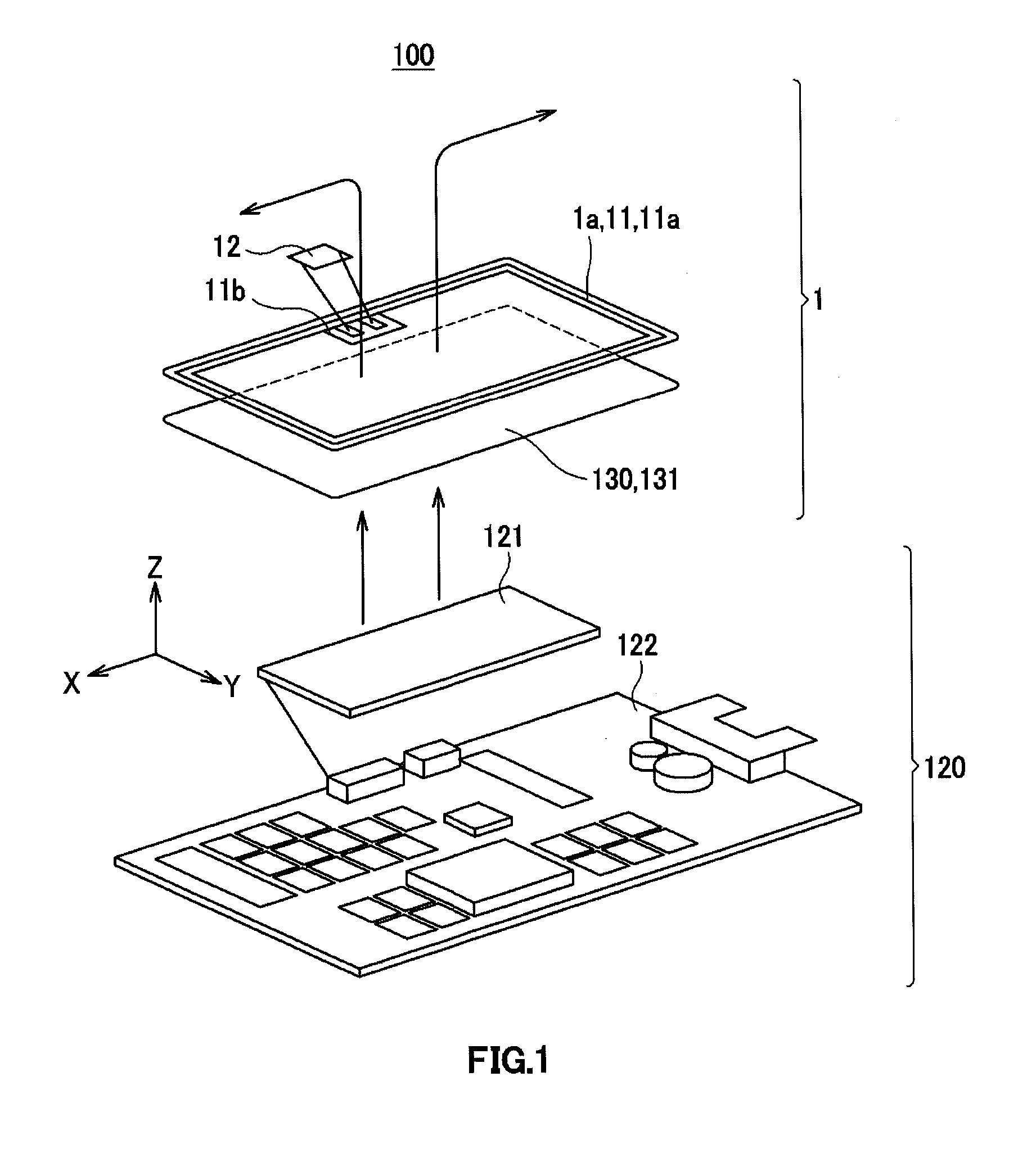
[0026]The communication apparatus according to one or more embodiments of the present invention may include an apparatus that is assembled into an electronic apparatus and can be communicated upon receip...


PUM


Abstract

An antenna apparatus is assembled into an electronic apparatus and made communicatable upon receipt of a magnetic field transmitted from a transmitter. The antenna apparatus includes an antenna substrate having an antenna coil inductively coupled to the transmitter formed thereon and a magnetic sheet for use in drawing the magnetic field transmitted from the transmitter to the antenna coil. The magnetic sheet is inserted into a center portion of the antenna coil such that two ends of the magnetic sheet are positioned closer to the center portion than two ends of the antenna coil in an inserting direction thereof.

Description

CROSS-REFERENCE TO RELATED APPLICATIONS[0001]This application is a National Stage application of International Patent Application No. PCT / JP2012 / 079631, filed on Nov. 15, 2012, and claims priority pursuant to 35 U.S.C. §119(a) to Japanese Patent Application No. P2011-260640, filed on Nov. 29, 2011. The international application and priority application are hereby incorporated by reference in their entirety.BACKGROUND OF INVENTION[0002]1. Field of the Invention[0003]One or more embodiments of the present invention relate to an antenna apparatus that is assembled into an electronic apparatus and can be communicated upon receipt of a magnetic field transmitted from a transmitter, and a communication apparatus.[0004]2. Background Art[0005]In electronic apparatuses such as portable telephones, an antenna module for an RFID (Radio Frequency Identification) has been used for installing a function for near non-contact communication therein.[0006]This antenna module carries out a communicati...

Claims


Application Information

Patent Timeline
Patent Type & Authority Applications(United States)
IPC IPC(8): H01Q7/06H01Q1/24
CPCH01Q1/24H01Q7/06H01Q1/38H01Q1/2225G06K19/07771
Inventor SAITO, NORIOSUGITA, SATORUIKEDA, YOSHITO
Owner DEXERIALS CORP
Why Eureka
Try Eureka