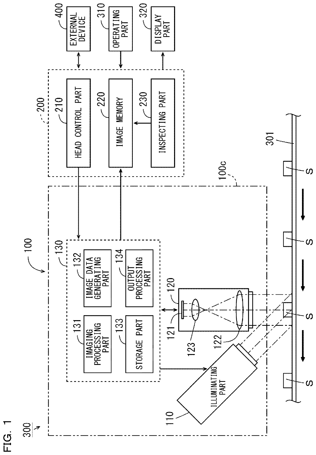
Inspection Device

a technology of inspection device and casing, which is applied in the field of inspection device, can solve the problems of difficult to grasp accurate information on the shape and surface state of the measurement target, and achieve the effects of reducing the installation space of the casing, facilitating the installation of the inspection device, and reducing the size of the casing

Active Publication Date: 2020-08-13
KEYENCE
View PDF0 Cites 1 Cited by
  • Summary
  • Abstract
  • Description
  • Claims
  • Application Information

AI Technical Summary

Benefits of technology

[0026]In this case, it is possible to compactly accommodate the plurality of the light projection and reception systems including the plurality of the light sources, the holding member, the reflecting member, the pattern generating part, the light projection optical system, the light reception optical system, and the imaging part, within the casing. This can downsize the casing, and can reduce an installation space for the casing. In addition, the handling such as the installation of the inspection device becomes easy.
[0027]According to the present invention, downsizing of the inspection device is implemented, and accurate grasping of the shape and the surface state of the measurement target becomes easy.

Problems solved by technology

This makes it difficult to grasp accurate information on the shape and the surface state of the measurement target.

Method used


Image

  • Inspection Device
  • Inspection Device
  • Inspection Device

Examples


embodiment

(5) Effect of Embodiment

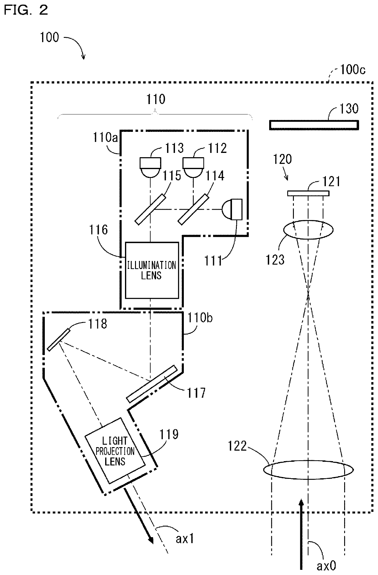
[0075](a) In the abovementioned head part 100, the green light, the blue light, and the red light are emitted from the plurality of the light sources 111, 112, and 113, and white light is generated. The generated white light enters the pattern generating part 118, whereby the measurement target S is successively irradiated by a plurality of pieces of structured light to be generated. In this process, the imaging part 120 successively receives the plurality of pieces of the structured light reflected from the measurement target S, and a plurality of pieces of pattern image data are successively generated. Height data is generated on the basis of the generated plurality of pieces of the pattern image data.

[0076]Moreover, the green light, the blue light, and the red light are successively emitted from the plurality of the light sources 111, 112, and 113, and enter the pattern generating part 118. In this process, the pattern generating part 118 reflects the gree...

modification examples

(7) Modification Examples

[0092](a) The head part 100 includes one illuminating part 110 and one imaging part 120, but the present invention is not limited thereto. FIG. 7 is a block diagram illustrating a configuration of the inspection device 300 according to a first modification example. As illustrated in FIG. 7, the head part 100 in the first modification example includes four illuminating parts 110. Note that, in FIG. 7, the illustration of the computing part 130 is omitted.

[0093]In the following explanation, when the four illuminating parts 110 are distinguished from one another, the four illuminating parts 110 are respectively referred to as illuminating parts 110A to 110D. The illuminating parts 110A to 110D mutually have the same structure, and are provided so as to surround the imaging part 120 at intervals of 90 degrees. Specifically, the illuminating part 110A and the illuminating part 110B are disposed so as to face each other by sandwiching the imaging part 120 therebet...


PUM


Abstract

An imaging part 120 receives the light that is reflected from the measurement target, and a plurality of pieces of pattern image data are generated. Height data is generated on the basis of the plurality of pieces of the pattern image data. Green light, blue light, and red light are successively emitted from the light sources 111 to 113, and are reflected from the pattern generating part 118, and uniform light of the green light, uniform light of the blue light, and uniform light of the red light are successively projected onto the measurement target. The imaging part 120 receives the uniform light reflected by the measurement target, and a plurality of pieces of texture image data are successively generated. The plurality of pieces of the texture image data are synthesized, whereby color texture image data is generated.

Description

CROSS-REFERENCE TO RELATED APPLICATIONS[0001]The present application claims foreign priority based on Japanese Patent Application No. 2019-021810, filed Feb. 8, 2019, the contents of which is incorporated herein by reference.BACKGROUND OF THE INVENTION1. Field of the Invention[0002]The present invention relates to an inspection device that inspects the height of a measurement target.2. Description of Related Art[0003]In an inspection device of a triangulation method, a light projecting part irradiates a surface of a measurement target with light, and a light receiving part including one-dimensionally or two-dimensionally arranged pixels receives the reflected light. Height data indicating a height image of the measurement target is generated on the basis of data on a received light amount distribution that is obtained by the light receiving part. Such height data is used in order to inspect (in-line inspect) the height of produced measurement targets in production sites such as fact...

Claims


Application Information

Patent Timeline
Patent Type & Authority Applications(United States)
IPC IPC(8): G06T7/521G06T15/04G01B11/25
CPCG01B11/2518G06T15/04G06T2207/10028G06T7/521G06T7/0004G06T7/586G06T2207/10152G06T2207/30164G01B11/2527G01B11/2536G01B11/2509G01N2021/845G01N21/8806G01N2021/8845G01N2021/8829G01N21/8851G01N2021/8887
Inventor ONO, SHUHEI
Owner KEYENCE
Why Eureka
Try Eureka