Eureka AIR delivers breakthrough ideas for toughest innovation challenges, trusted by R&D personnel around the world.

Chain transmission

a chain and chain technology, applied in the direction of driving chains, belts/chains/gearrings, driving chains, etc., can solve the problems of reducing the durability of guides and plates, and achieve the effect of reducing friction loss

Active Publication Date: 2014-10-30
TSUBAKIMOTO CHAIN CO
View PDF11 Cites 1 Cited by
  • Summary
  • Abstract
  • Description
  • Claims
  • Application Information

AI Technical Summary

Benefits of technology

The present invention is aimed at reducing friction loss in the transmission of power without compromising the durability of the chain guide mechanism and the chain. This is achieved by using plates in the chain that have specific backside heights and radii of curvature, which reduce the number of plates in contact with the chain and minimize friction loss when the chain is guided by the first or second guide. Additionally, a third plate with specific backside height is used to further reduce friction loss by reducing the contact area between the chain and guides. Overall, the invention results in reduced friction loss and improved durability of the chain guide mechanism and the chain.

Problems solved by technology

There was thus a problem in that, in some areas of contact between the guides and plates, where the radius of curvature of the guides is small, the contact pressure therebetween could become excessive, and this results in a reduction in durability of the guides and plates.

Method used


Image

  • Chain transmission
  • Chain transmission
  • Chain transmission

Examples


embodiment

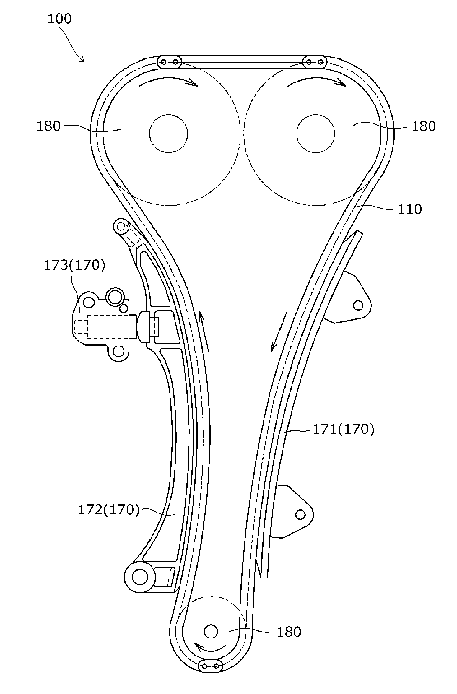
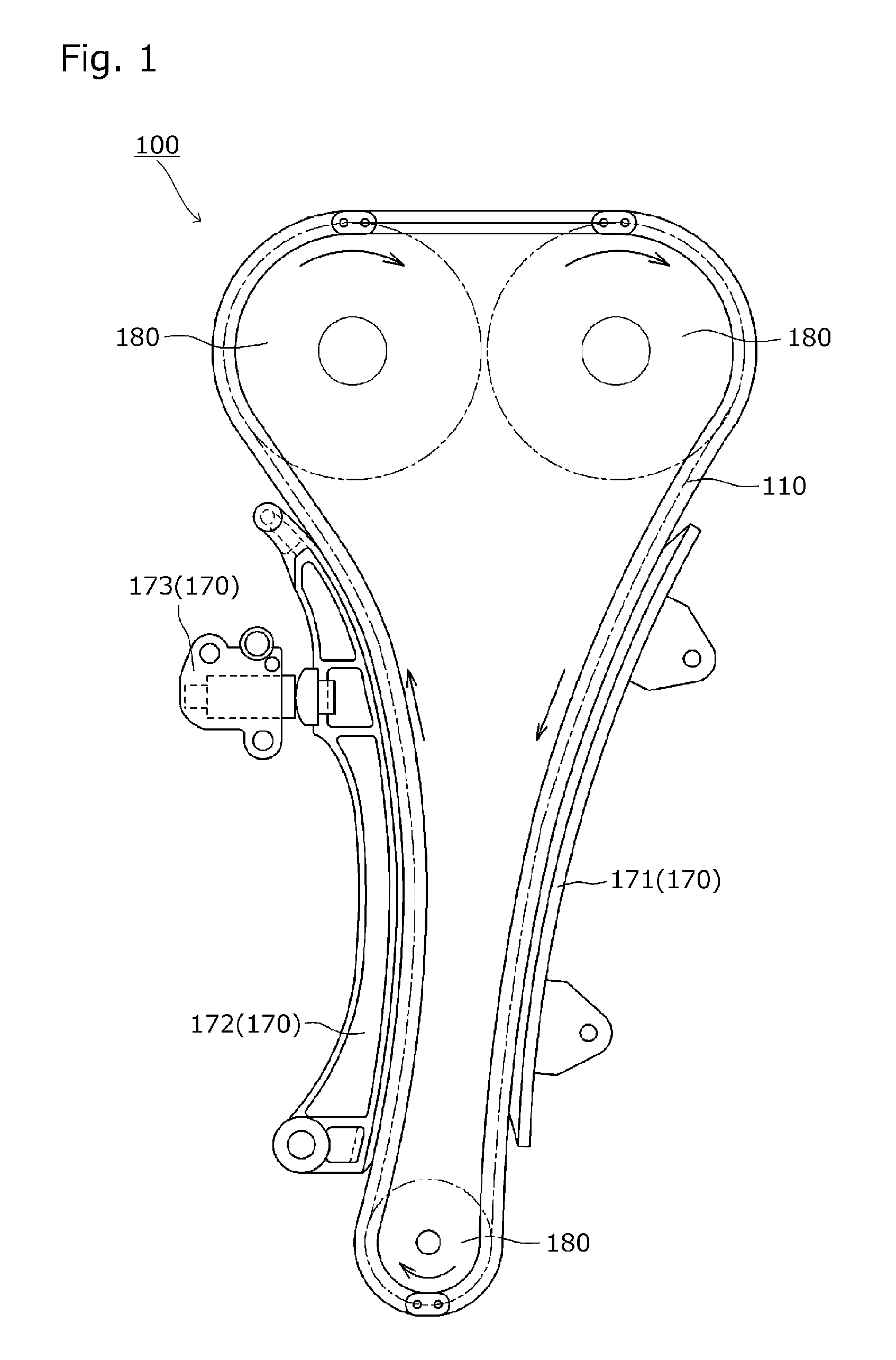
[0029]A chain transmission 100 according to one embodiment of the present invention will be hereinafter described with reference to the drawings.

[0030]The chain transmission 100 is designed as a timing chain system of a car engine, and includes, as shown in FIG. 1, sprockets 180 mounted to a crankshaft and a camshaft inside an engine room, a chain 110 passing over the sprockets 180, and a chain guide mechanism 170 that guides the chain 110 in sliding contact therewith.

[0031]The chain guide mechanism 170 is formed by a fixed guide 171 fixed to the engine block for guiding the chain 110, a pivot guide 172 pivotally attached to the engine block for guiding the chain 110, and a tensioner 173 that presses the pivot guide 172 to give an appropriate tension to the chain 110, as shown in FIG. 1.

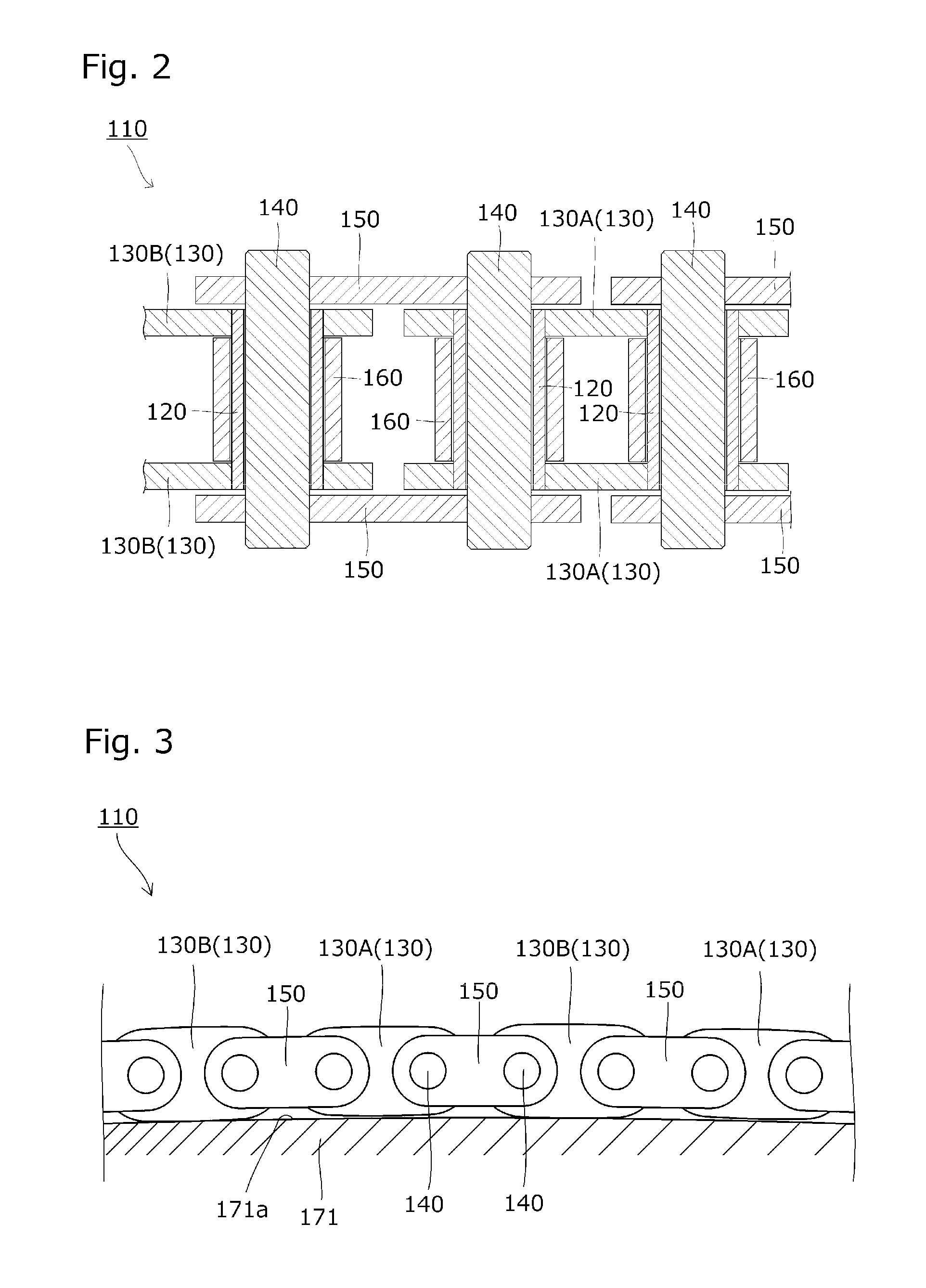
[0032]The fixed guide 171 has a first guide 171a formed as a shoe surface for guiding the chain 110 in sliding contact therewith as shown in FIG. 3 or FIG. 4. The pivot guide 172 has a second guide 1...


PUM


Abstract

A chain transmission is provided which is capable of reducing friction loss in the transmission of power without the risk of compromising the durability of a chain guide mechanism and the chain. The chain transmission includes a chain and a chain guide mechanism. The chain guide mechanism includes a first guide and a second guide having a smaller radius of curvature than that of the first guide. The plurality of plates include a first plate and a second plate. The first plate has a backside height set such that the first plate does not contact the first guide when the first plate is guided by the first guide and such that the first plate contacts the second guide when the first plate is guided by the second guide.

Description

BACKGROUND OF THE INVENTION[0001]1. Field of the Invention[0002]The present invention relates to a chain transmission including a chain having a plurality of plates and a chain guide mechanism that guides the chain in sliding contact therewith.[0003]2. Description of the Related Art[0004]Conventionally known timing chain systems for car engines (see, for example, Japanese Patent Application Laid-open No. 2007-107583) include, for example, a chain transmission including a chain having a plurality of plates and a chain guide mechanism.[0005]This known timing chain system is made up of sprockets mounted to a crankshaft and a camshaft inside an engine room, a chain passing over the sprockets, a fixed guide fixed to the engine block for guiding the chain, a pivot guide pivotally attached to the engine block for guiding the chain, and a tensioner that presses the pivot guide to give an appropriate tension to the chain.[0006]In the chain described in Japanese Patent Application Laid-open N...

Claims


Application Information

Patent Timeline
IPC IPC(8): F16H7/06F16H7/18
CPCF16H7/06F16H2007/185F16H7/18F16G13/07F16G15/12F16G13/06F02B67/06
Inventor KUREMATSU, YUJIYOKOYAMA, MASANORI
Owner TSUBAKIMOTO CHAIN CO
Why Eureka
Eureka Blog
Learn More