Tile levelling device

a technology for levelling and spacing tiles, which is applied in the direction of roofs, roofing, roof tools, etc., can solve the problems of reducing or restricting the transfer of force between adjacent tiles, and the proportions of spacer bodies are not aligned, so as to achieve the effect of reducing or limiting the flexibility of each spacer body

Inactive Publication Date: 2014-11-06
ART PLASTICS
View PDF14 Cites 58 Cited by
  • Summary
  • Abstract
  • Description
  • Claims
  • Application Information

AI Technical Summary

Benefits of technology

[0012]In an alternate embodiment of the present invention, at least one of the spacer bodies, and preferably most or all of the spacer bodies includes both a first engagement portion and a second engagement portion. Each of the spacer bodies are therefore configured to extend the distance between and, in use, space apart a pair of adjacent tiles. The first spacer portion and the second spacer portion of the spacer body or bodies are preferably laterally spaced apart relative to a longitudinal axis of the base plate about which the central hub and each spacer body extends. Each of the spacer bodies is preferably flexible allowing the spacer bodies to flex when a load is applied by an abutting tile. Thus, while a mechanical connection is made between the two adjacent tiles, the flexibility of each of the spacer body reduces or limits the transfer of force between these adjacent tiles.
[0014]The spacer bodies of each embodiment extend outwardly, preferably generally perpendicularly outwardly, from the upper surface of the base plate. Each spacer body is preferably flexible and can be configured to bend and / or flex relative to the base plate. In some cases, each spacer body is configured to transversely bend and / or flex relative to a longitudinal or transverse axis that the respective spacer body is aligned. This flexibility allows the spacer bodies to flex when a load is applied by an abutting tile. Loaded parts of the tile levelling and spacing device, such as the spacer bodies, can therefore flex or otherwise move with that applied load. This reduces damage, such as cracks or the like, that may otherwise occur if the tile levelling and spacing device was constructed from a more rigid material.
[0017]The dimensions of the spacer bodies can be optimised to minimise mechanical connection between two adjacent tiles. For example, the thickness of the spacer bodies can be selected to be less than ⅔ the tile spacing between adjacent tiles. More preferably, the thickness of the spacer bodies can be selected to be less than less than ½ the tile spacing between adjacent tiles. Similarly, the height of the spacer bodies relative to the upper surface of the base plate can be selected to be less than the thickness of tiles the tile levelling and spacing device has been selected to be used to space and level. Preferably, the height of the spacer bodies relative to the upper surface of the base plate would be less than ⅔ the thickness of those tiles. More preferably, the height of the spacer bodies relative to the upper surface of the base plate would be less than ½ the thickness of those tiles.
[0023]The central hub can have any configuration in which the stem aperture can be located. The central hub is preferably configured to bend and / or flex relative to the base plate. Furthermore, the width of the central hub about the lengthwise axis of the base plate is preferably less than the spacing between adjacent tiles. These dimensions ensure the central hub does not abut the sides of the tiles which in use abut the spacer bodies and thereby bridge the gap between those tiles.

Problems solved by technology

However, the engagement portions of the spacer bodies are not aligned.
Thus, while a mechanical connection is made between the two adjacent tiles, the flexibility of each of the spacer body reduces or limits the transfer of force between these adjacent tiles.

Method used


Image

  • Tile levelling device
  • Tile levelling device
  • Tile levelling device

Examples


Embodiment Construction

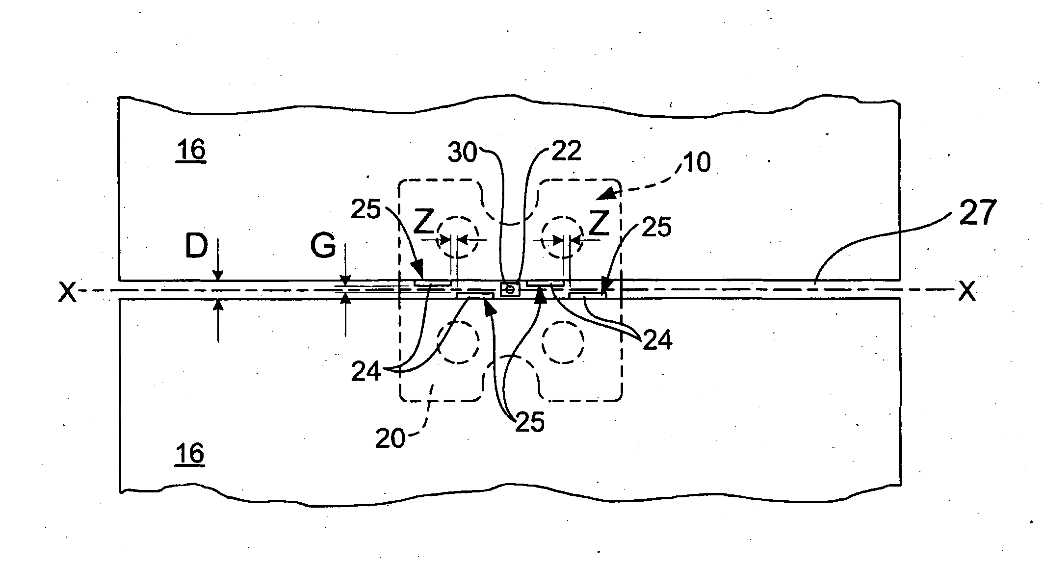
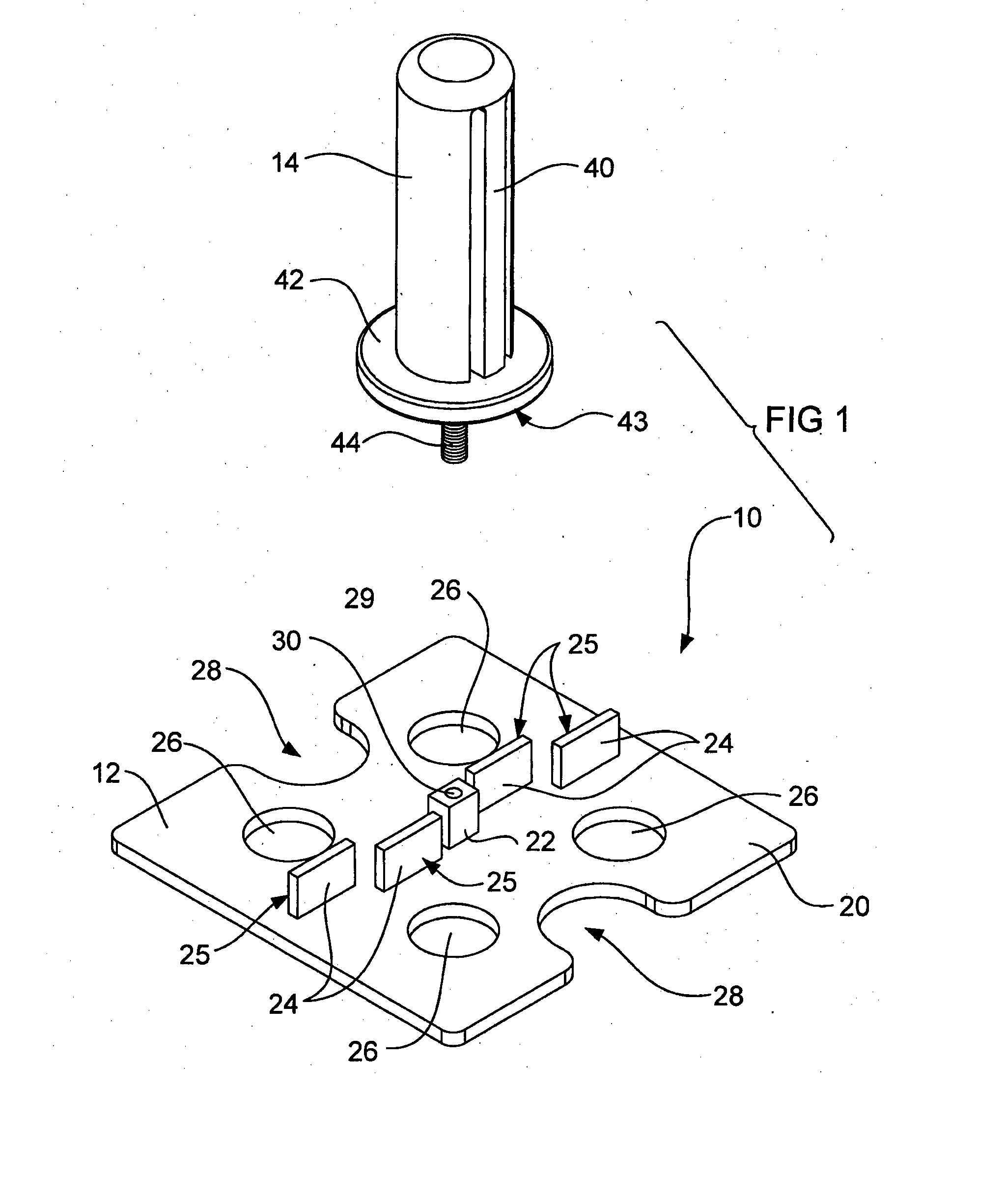
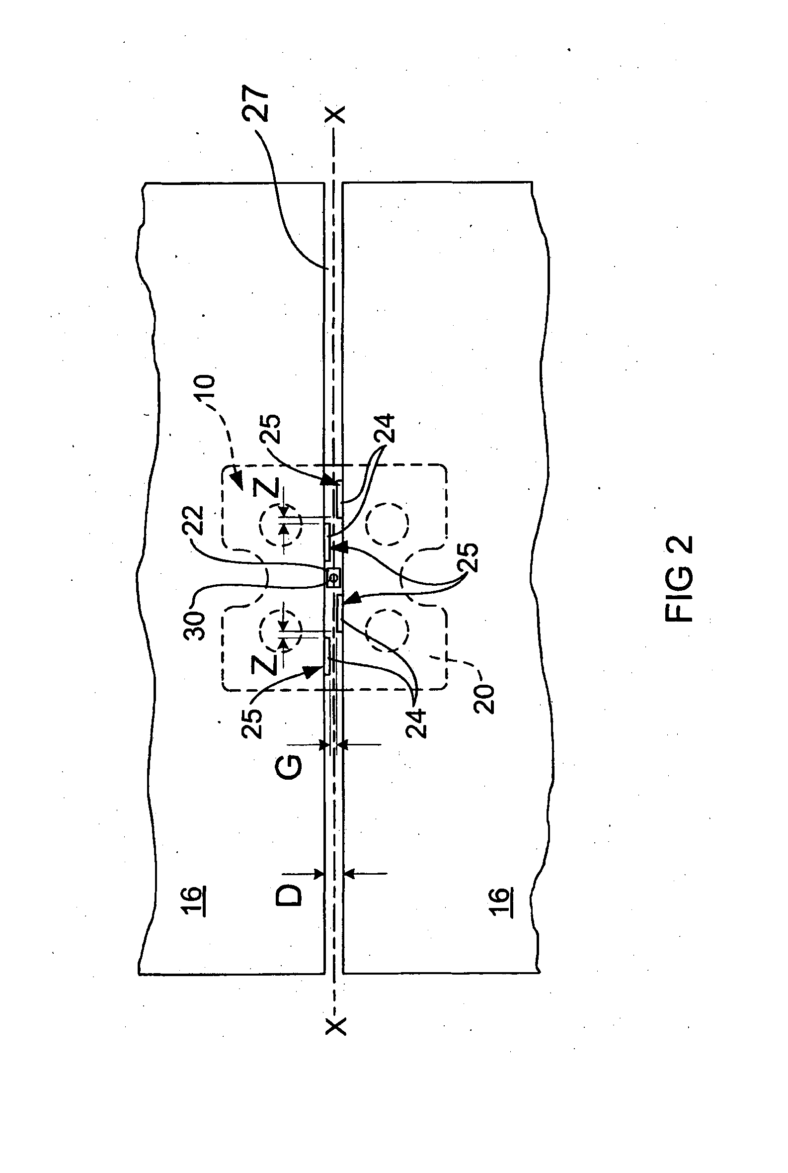
[0046]Referring firstly to FIGS. 1 and 2, there is shown a tile levelling and spacing system 10 according to a first preferred embodiment of the present invention. The tile levelling and spacing system 10 comprises a tile levelling and spacing device 12 and a clamping spindle 14. The tile levelling and spacing device 12 and a clamping spindle 14 act cooperatively to clamp around a tile 16 (FIG. 2) when in use.

[0047]The illustrated tile levelling and spacing device 12 comprises a generally square moulded body made of a plastic material fabricated in a plastic injection moulding process or similar. The device 12 includes a rectangular base plate 20, a square central connection hub 22, and four spacing tabs 24. The base plate 20, central connection hub 22 and spacing tabs are all integrally moulded as part of the device 12 during a plastic moulding process. It should be appreciated that the dimensions of the features of the device 12 can vary to suit a particular tile size and configur...


PUM


Abstract

A tile levelling and spacing device (12) including: a base plate (20) having an upper surface (29) and a base surface; a central hub (22) which includes a stem aperture, each centrally located in the base plate (20), the stem aperture including internal threading; and at least one spacer body (24) which extend outwardly from the upper surface (20) of the base plate (20), wherein the at least one spacer body (24) includes: at least one first engagement portion (25) which is configured to abut against a side of a first tile of a pair of adjacent tiles (16) and be spaced away from the side of the second tile of that pair of tiles (16); and at least one second engagement portion (25) which is configured to abut against a side of the second tile of the pair of adjacent tiles (16) and be spaced away from the side of the first tile of that pair of tiles (16).

Description

FIELD OF THE INVENTION[0001]The present invention generally relates to a tile levelling and spacing device. The invention is particularly applicable for spacing and levelling floor or wall tiles and it will be convenient to hereinafter disclose the invention in relation to that exemplary application. However, it is to be appreciated that the invention is not limited to that application and could be used for any tiling or paving application that requires one or more tiling or paving bodies used in an installation to be properly spaced apart from other tiling or paving bodies and level with other tiling or paving bodies.BACKGROUND OF THE INVENTION[0002]The following discussion of the background to the invention is intended to facilitate an understanding of the invention. However, it should be appreciated that the discussion is not an acknowledgement or admission that any of the material referred to was published, known or part of the common general knowledge as at the priority date of...

Claims


Application Information

Patent Timeline
Patent Type & Authority Applications(United States)
IPC IPC(8): E04F21/00E04F21/22
CPCE04F21/0092E04F21/22
Inventor PSAILA, ANTHONYPSAILA, ANDY NICHOLAS
Owner ART PLASTICS
Why Eureka
Try Eureka