
Motor Grader Cross Slope Control With Articulation Compensation

Inactive Publication Date: 2014-11-06
CATERPILLAR INC
View PDF7 Cites 21 Cited by
  • Summary
  • Abstract
  • Description
  • Claims
  • Application Information

AI Technical Summary

Benefits of technology

The patent text describes a method and system for controlling a blade of a motor grader to achieve a desired cross slope cut angle. The system includes sensors and a controller that adjusts the cross slope angle of the blade to match the desired angle. This is done by identifying the direction of travel of the blade and generating a projection of the blade edge onto a perpendicular surface. By measuring the angle of the cut projection and adjusting the cross slope angle of the blade, the method ensures precise control over the cross slope cut angle. Overall, the technology allows for accurate and efficient cutting of slopes using the motor grader blade.

Problems solved by technology

Given the variabilities in blade position, frame articulation, and wheel steering, it can be difficult for the operator to position the blade to produce a precise cut.
The difficulty in maintaining an accurate blade position during such a task is increased when the motor grader frame is also articulated, for example, when the machine is crabbing or turning.
However, the system of the '145 patent is fairly complex in implementation, requiring additional machine sensors, and is thus expensive and prone to errors or failures.
In addition, calculating the blade orientation in the manner set forth in the '145 patent may not accurately account for non-transverse gravitational effects such as water run-off paths.

Method used


Image

  • Motor Grader Cross Slope Control With Articulation Compensation
  • Motor Grader Cross Slope Control With Articulation Compensation
  • Motor Grader Cross Slope Control With Articulation Compensation

Examples


Embodiment Construction

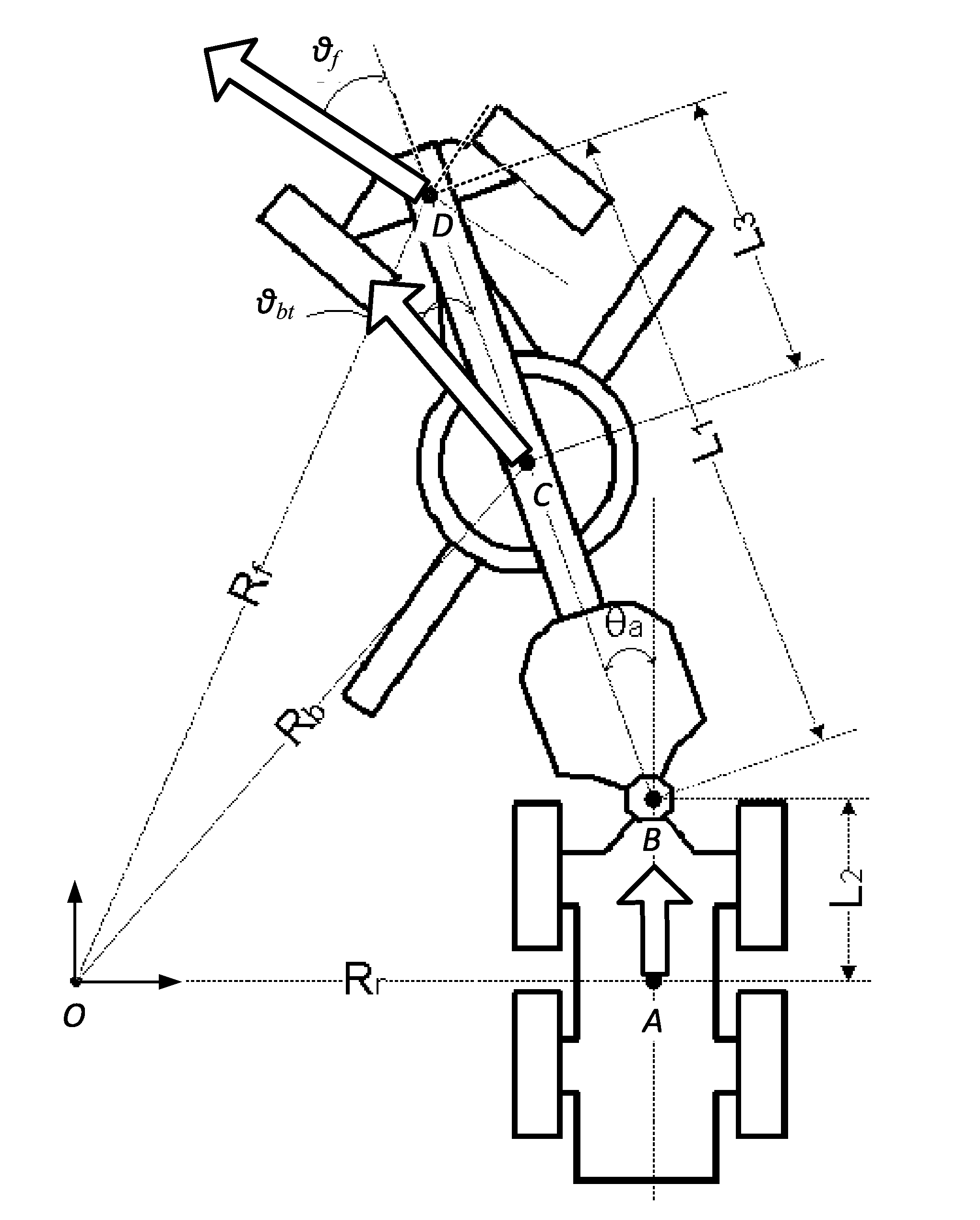
[0019]The present disclosure provides a system and method for motor grader blade control that compensates for machine pitch, roll, steering and articulation to replicate a desired cross slope cut angle in the earth being shaped. In particular, the cross slope angle of the blade is adjusted pursuant to a pure pursuit method, so that the actual cross slope cut angle corresponds to the desired cross slope cut angle. The controller receives a signal indicative of the desired cross slope cut angle and executes a pure pursuit procedure to identify the blade cross slope angle needed to yield the desired cross slope cut angle, while accounting for machine attitude and configuration. In simplified overview, the pure pursuit procedure includes identifying a blade travel direction, and identifying a horizontal component thereof. The blade edge is projected onto a plane perpendicular to the horizontal component of the blade travel direction and generating a slope function specifying the cross s...


PUM


Abstract

A motor grader is provided having cross slope cut angle control for providing accurate cuts generally, and particularly while the machine is travelling in other than a straight and level fashion. A controller is configured to adjust the cross slope angle of the blade, so that the cross slope cut angle corresponds to a desired cross slope cut angle. The controller receives a signal indicative of the desired cross slope cut angle and executing a pure pursuit procedure to identify a blade cross slope angle to yield the desired cross slope cut angle. The pure pursuit procedure includes identifying a blade travel direction, and identifying a horizontal component thereof. The blade edge is projected onto a plane perpendicular to the horizontal component of the blade travel direction, generating a slope function specifying the cross slope cut angle as a function of blade cross slope angle.

Description

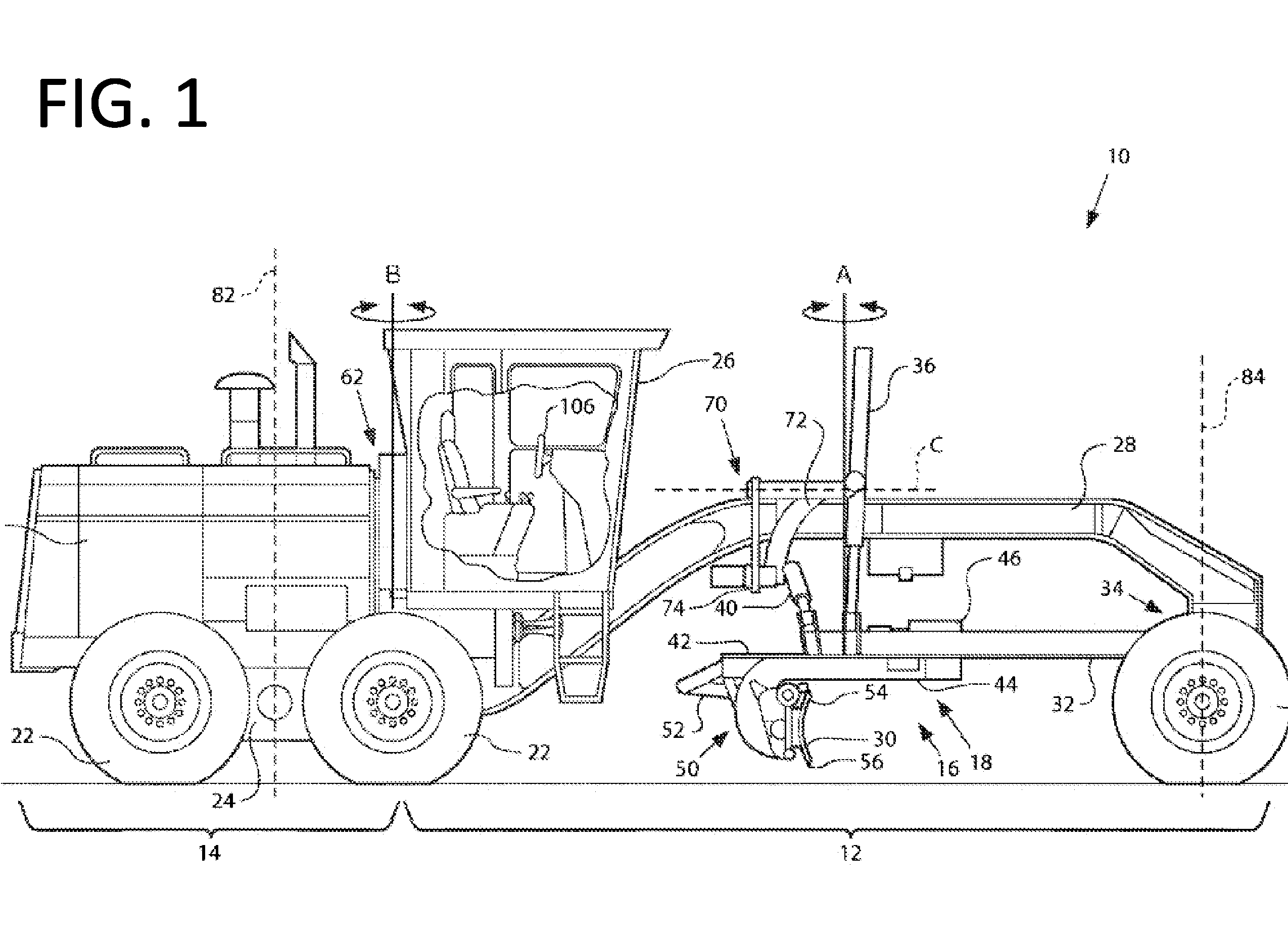
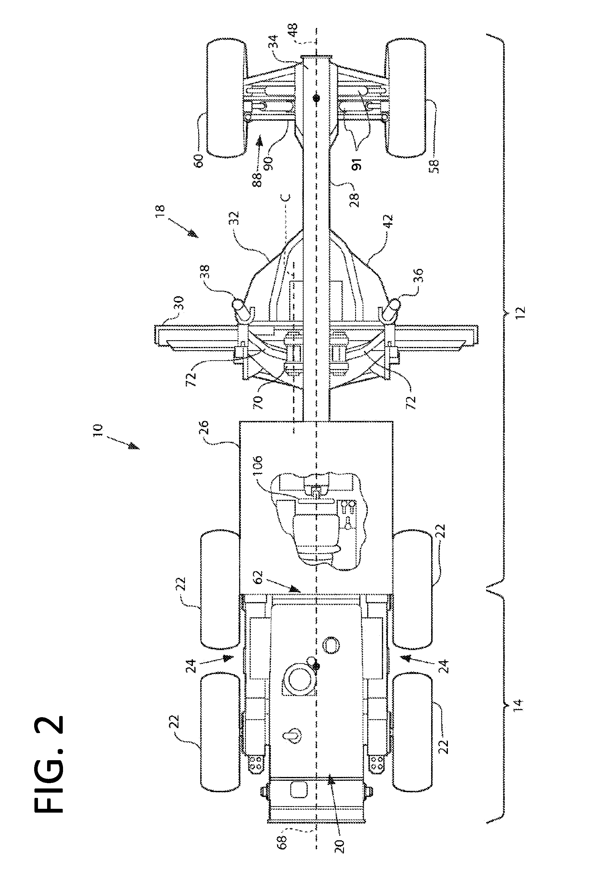
TECHNICAL FIELD OF THE DISCLOSURE[0001]The present disclosure relates to motor grader operation and, more particularly, relates to motor grader blade control for maintaining accurate cut control during cross slope operations.BACKGROUND OF THE DISCLOSURE[0002]Motor graders are earth-moving machines that are employed in a variety of tasks, including as shaping tools to create banks, ditches, and berms, as surface preparation tools for scarification and other surface treatments, and as finishing tools to refine construction site surfaces and roadway surfaces to final shape and contour. Although not universally applicable, motor graders typically include a front frame and a rear frame that are joined at an articulation joint. The rear frame includes compartments for housing the power source and cooling components, the power source being operatively coupled to the rear wheels for primary propulsion of the machine. The rear wheels are typically arranged in tandem sets on opposing sides of...

Claims


Application Information

Patent Timeline
IPC IPC(8): E02F3/84
CPCE02F3/844E02F3/764E02F3/7645E02F3/765E02F3/7654E02F3/845E02F9/0841
Inventor ZHU, YONGLIANGPERSCHBACHER, JESSICA
Owner CATERPILLAR INC
Learn More