Radiographic system and control method thereof

a technology of a radiographic system and a control method, applied in the field of radiographic systems, can solve problems such as physical fatigue of operators, and achieve the effect of reducing driving forces

Active Publication Date: 2014-11-06
SAMSUNG ELECTRONICS CO LTD
View PDF5 Cites 28 Cited by
  • Summary
  • Abstract
  • Description
  • Claims
  • Application Information

AI Technical Summary

Benefits of technology

[0030]The system control unit may be further configured to reduce the ratio of the moving speed of the photographic unit to the force applied to the photographic unit in response to the moving speed of the photographic unit being less than or equal to the second reference speed.
[0031]The radiographic system may further include a measurement unit configured to measure a magnitude and a direction of an external force applied to the photographic unit; and a drive unit configured to move the photographic unit based on the magnitude and the direction of the external force measured by the measurement unit and the ratio of the moving speed of the photographic unit to the force applied to the photographic unit; wherein the system control unit may be further configured to reduce the ratio of the moving speed of the photographic unit to the force applied to the photographic unit as the moving speed of the photographic unit decreases in response to the moving speed of the photographic unit being less or equal to the second reference speed, thereby causing the drive unit to reduce a driving force for moving the photographic unit as the moving speed of the photographic unit decreases in response to the moving speed of the photographic unit being less or equal to the second reference speed.

Problems solved by technology

Accordingly, when there is a need for a repetitive movement of the X-ray tube, the operator may experience physical fatigue.

Method used


Image

  • Radiographic system and control method thereof
  • Radiographic system and control method thereof
  • Radiographic system and control method thereof

Examples


Embodiment Construction

[0058]The following detailed description is provided to assist the reader in gaining a comprehensive understanding of the methods, apparatuses, and / or systems described herein. However, various changes, modifications, and equivalents of the methods, apparatuses, and / or systems described herein will be apparent to one of ordinary skill in the art. Also, descriptions of functions and constructions that are well known to one of ordinary skill in the art may be omitted for increased clarity and conciseness.

[0059]Throughout the drawings and the detailed description, the same reference numerals refer to the same elements. The drawings may not be to scale, and the relative size, proportions, and depiction of elements in the drawings may be exaggerated for clarity, illustration, and convenience.

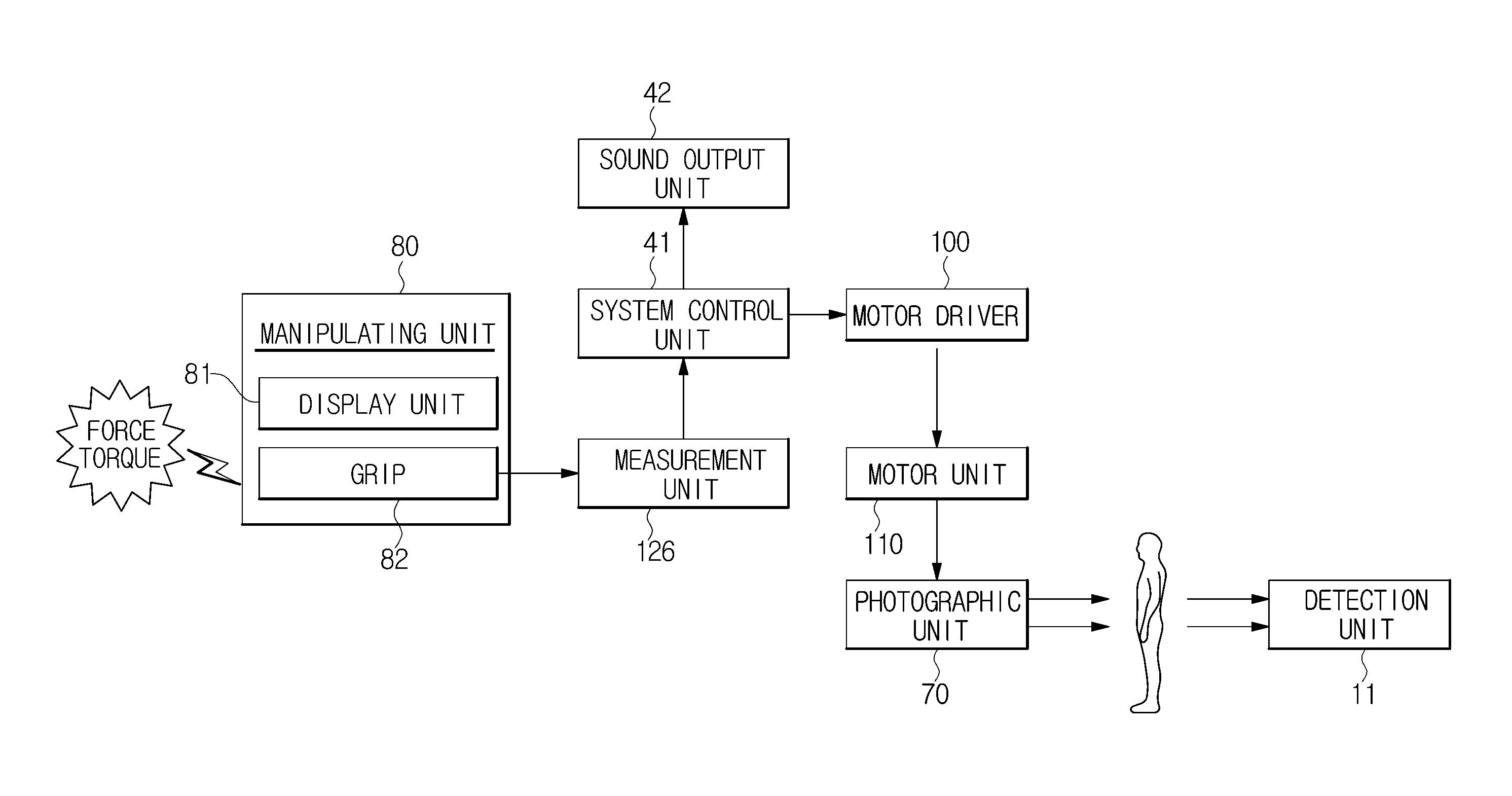
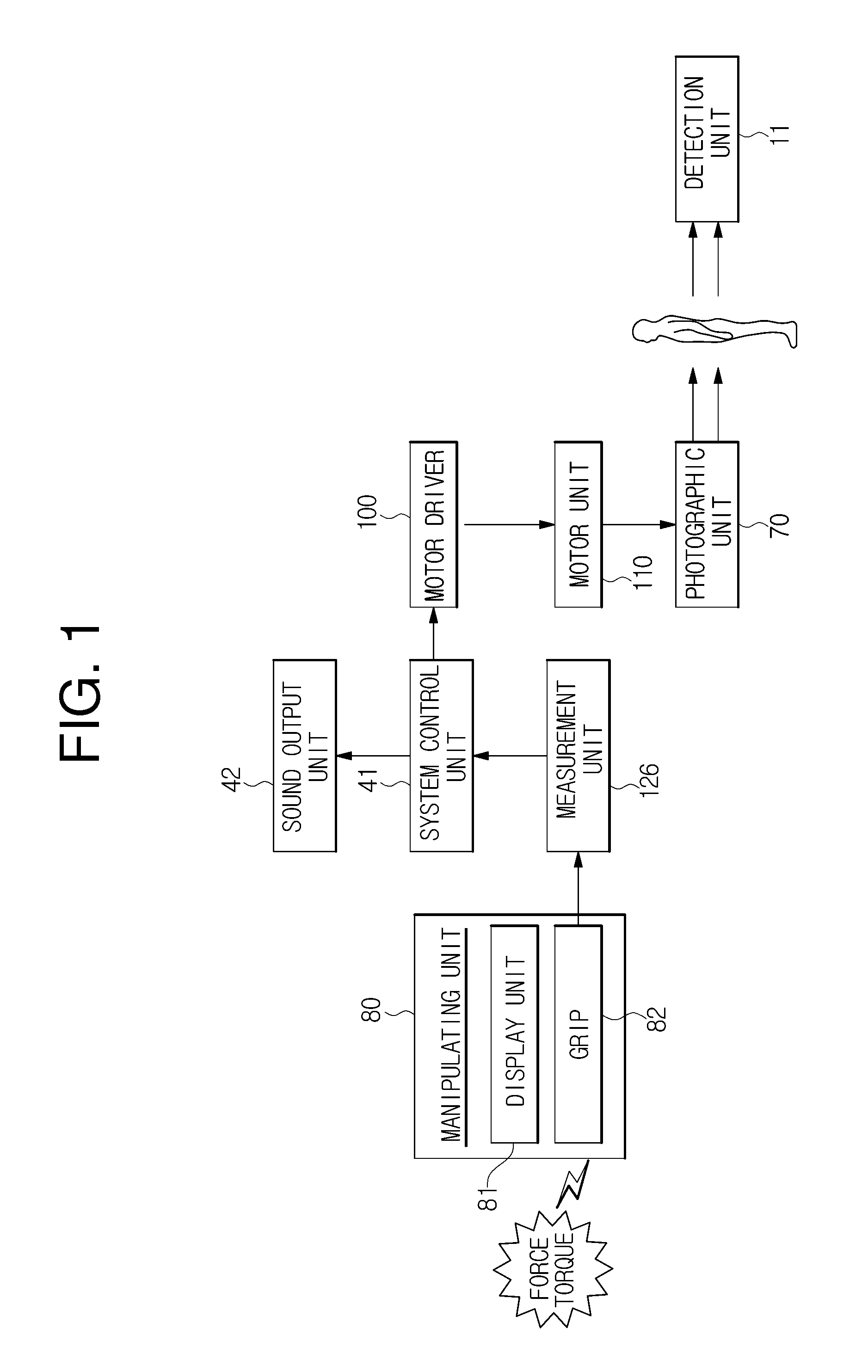
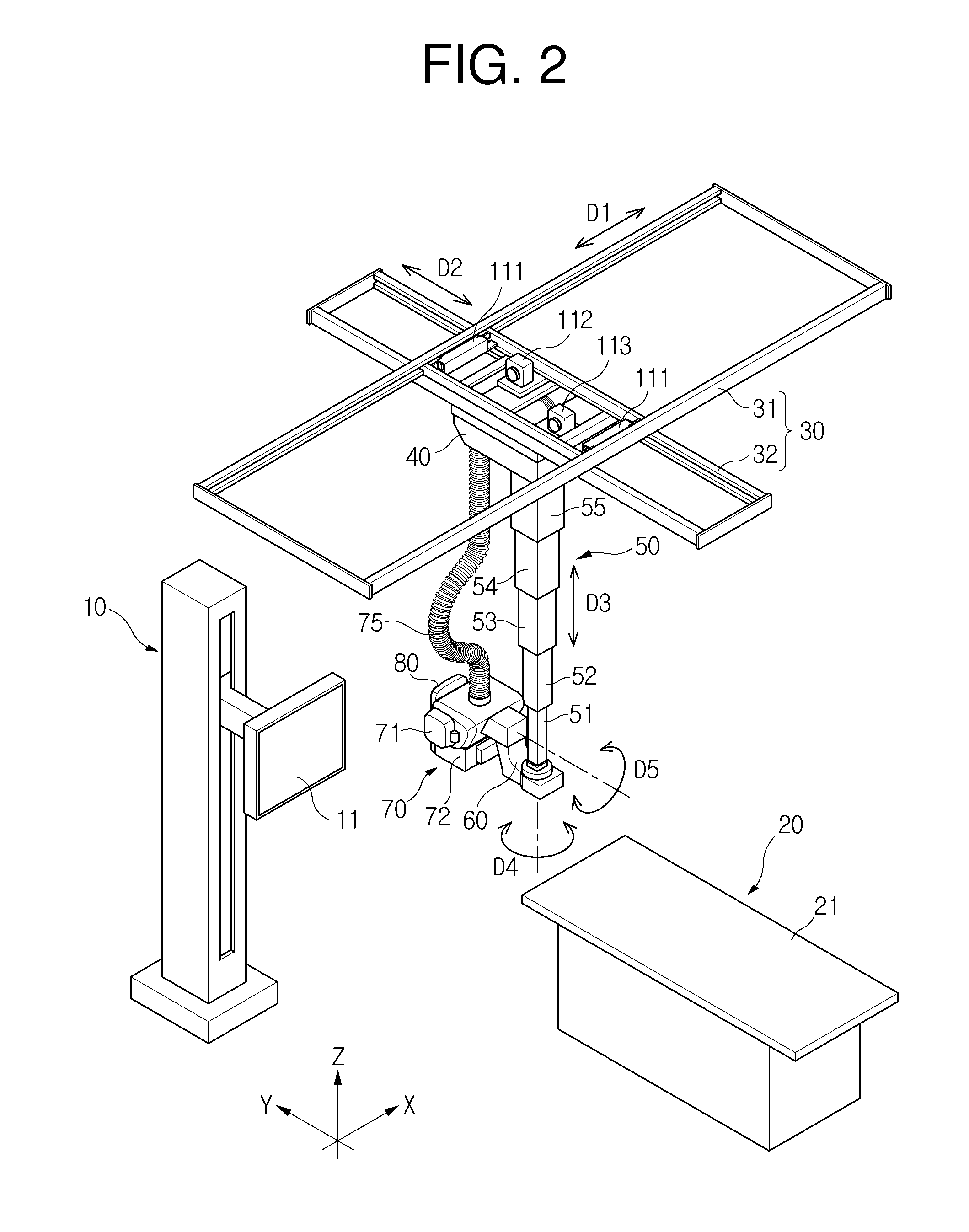
[0060]FIG. 1 is a block diagram illustrating the configuration of a radiographic system in accordance with one example. FIG. 2 is a perspective view illustrating the configuration of the radiographic...


PUM

PropertyMeasurementUnit
external forceaaaaaaaaaa
rotation angleaaaaaaaaaa
resonance frequencyaaaaaaaaaa

Abstract

A radiographic system includes a photographic unit; an operating panel including a button configured to be pressed to indicate that a movement direction of the photographic unit is to be limited to a specific movement direction; a measurement unit provided between the operating panel and the photographic unit and configured to measure a magnitude and a direction of an external force applied to the operating panel; and a drive unit configured to move the photographic unit only in the specific movement direction based on the magnitude and the direction of the external force measured by the measurement unit in response to the button being pressed.

Description

CROSS-REFERENCE TO RELATED APPLICATIONS[0001]This application is a continuation-in-part of application Ser. No. 13 / 738,221 filed on Jan. 10, 2013, which is a continuation-in-part of application Ser. No. 13 / 237,219 filed on Sep. 20, 2011, now U.S. Pat. No. 8,651,740 issued on Feb. 18, 2014. This application claims the benefit of Korean Patent Application No. 10-2010-0097304 filed on Oct. 6, 2010, in the Korean Intellectual Property Office. The disclosures of application Ser. Nos. 13 / 738,221 and 13 / 237,219 and Korean Patent Application No. 10-2010-0097304 are incorporated herein by reference in their entirety for all purposes.BACKGROUND[0002]1. Field[0003]This application relates to a radiographic system that can be moved by an operator using a reduced force and a control method thereof.[0004]2. Description of Related Art[0005]A radiographic system is designed to obtain an internal image of a human body using X-rays. The radiographic system is used to inspect injuries of an internal p...

Claims


Application Information

Patent Timeline
Patent Type & Authority Applications(United States)
IPC IPC(8): A61B19/00
CPCA61B19/56A61B6/462A61B6/102A61B6/4458A61B6/469A61B6/4452G01L5/22A61B6/0407A61B6/4464A61B6/4476A61B6/4482A61B6/467A61B6/547
Inventor LEE, DONG JAEYANG, SOO SANGLEE, HYEON MINLEE, JEONG PILHAN, WOO SUPHWANG, HYUN WOONGSHIN, SEUNG HOONHWANG, DO HYEONGHER, JONG BEOM
Owner SAMSUNG ELECTRONICS CO LTD
Why Eureka
Try Eureka