Control device

a control device and control technology, applied in the direction of electric devices, engine-driven generators, transportation and packaging, etc., can solve the problem of inability to appropriately perform speed control, and achieve the effect of reducing the transmission path of shocks

Active Publication Date: 2014-11-06
AISIN AW CO LTD
View PDF8 Cites 4 Cited by
  • Summary
  • Abstract
  • Description
  • Claims
  • Application Information

AI Technical Summary

Benefits of technology

[0015]With this structure, when the subject control ends, the direct-coupling engagement control is performed that gradually increases the engagement pressure of the first engagement device from the slip engagement pressure to the direct-coupling engagement pressure. This can keep a shock from being transmitted to the power transmission path when the direct-coupling engagement control starts.
[0016]Furthermore, with the above-described structure, the direct-coupling pressure increasing control to gradually increase the engagement pressure from the mid-control set pressure to the post-control set pressure is also performed for the second engagement device that can be brought into the slipping engaged state in place of the first engagement device. This direct-coupling pressure increasing control is performed while the direct-coupling engagement control of the first engagement device is performed. As a result, also when the second engagement device is in the slipping engaged state while the subject control is preformed, the transmission of a shock to the power transmission path can be reduced when the slip rotational speed control ends.

Problems solved by technology

In this state, the slip rotational speed control cannot appropriately be performed, so a largely fluctuating driving force may be transmitted to the wheels.

Method used


Image

  • Control device
  • Control device
  • Control device

Examples


Embodiment Construction

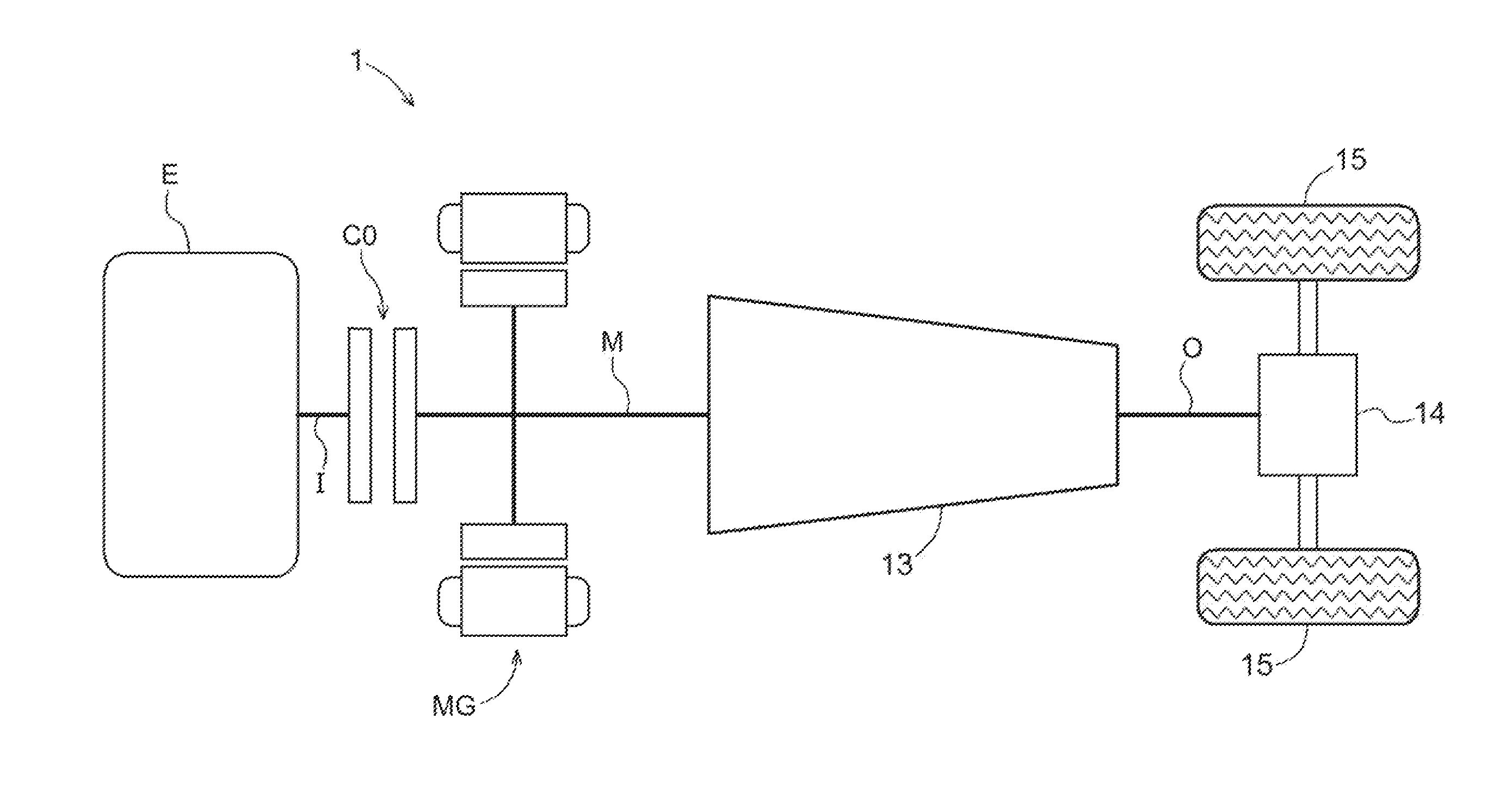
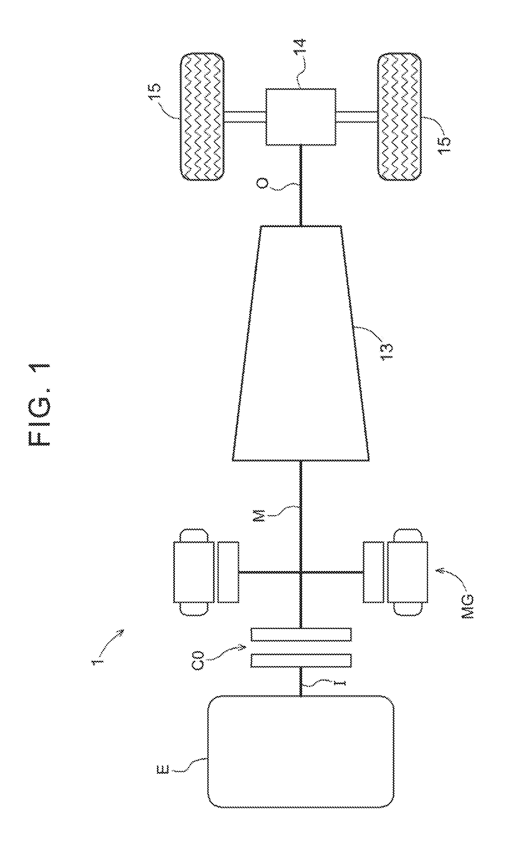
[0034]An embodiment of a control device according to the present invention will be described with reference to the accompanying drawings. A control device 3 according to the present embodiment controls a drive device 1. In the present embodiment, as shown in FIG. 1, the drive device 1 is a drive device for a vehicle (drive device for a hybrid vehicle) for driving a vehicle (hybrid vehicle) equipped with both an internal combustion engine E and a rotary electric machine MG as a driving force source of wheels 15. The control device 3 according to the present embodiment will be described below in detail.

[0035]In the following description, the term “drivingly coupled” means a state in which two rotational members are coupled so as to be capable of transmitting a driving force (synonymous with torque), and is used as a concept that includes a state in which the two rotational members are coupled so as to rotate in an integrated manner, or a state in which the two rotational members are c...


PUM


Abstract

A control device for a vehicle. While subject control is performed, a second engagement control unit controls the engagement pressure of the second engagement device to a mid-control set pressure that has been set to be equal to or more than a first engagement pressure and equal to or less than a second engagement pressure. The first engagement pressure is a lower limit engagement pressure capable of maintaining the second engagement device in the directly coupled engaged state, in a state in which requested torque that is torque required to be transmitted to the wheels is transmitted to the wheels. The second engagement pressure is a lower limit engagement pressure capable of maintaining the second engagement device in the directly coupled engaged state, in a state in which maximum output torque of the rotary electric machine is transmitted to the wheels.

Description

TECHNICAL FIELD [0001]The present invention relates to a control device that controls a drive device for a vehicle provided with a speed change mechanism in a power transmission path connecting a rotary electric machine and wheels, and also provided with a plurality of engagement devices in the power transmission path.BACKGROUND ART [0002]As a control device that controls a drive device for a vehicle as a controlled object as described above, for example, a device described in Japanese Patent Application Publication No. 2010-030486 (JP 2010-030486 A) (Patent Document 1) is already known. This control device is structured to be capable of performing slip rotational speed control such that an engagement device (second clutch CL2 in Patent Document 1) provided between a rotary electric machine and wheels is brought into a slipping engaged state, and the rotational speed of the rotary electric machine approaches a target rotational speed. In this case, the target rotational speed is set...

Claims


Application Information

Patent Timeline
Patent Type & Authority Applications(United States)
IPC IPC(8): B60W20/00B60L50/16
CPCB60W20/40Y10S903/902F16H2200/0052B60K6/48B60K6/547B60W10/02B60W10/06B60W10/08B60L3/102B60L3/106B60L15/2009B60L15/2054B60W10/115Y02T10/72Y02T10/62Y02T10/64
Inventor MATOBA, JYUNICHIKUSAMIZU, TOMOHIRO
Owner AISIN AW CO LTD
Why Eureka
Try Eureka