Method and Device for Determining the Installation Position of a Sensor Module in a Vehicle, and Vehicle Having Such a Device

a sensor module and installation position technology, which is applied in the direction of braking systems, instruments, braking components, etc., can solve the problems of improper installation location, sensor module may not be installed at its original location, and sensor module may be accidentally attached to the transverse beam, so as to improve the determination of the installation position of sensor modules

Active Publication Date: 2014-11-06
ZF CV SYST EURO BV
View PDF5 Cites 8 Cited by
  • Summary
  • Abstract
  • Description
  • Claims
  • Application Information

AI Technical Summary

Benefits of technology

[0004]Generally speaking, it is an object of the present invention to improve the determination of the installation position of sensor modules in a vehicle.

Problems solved by technology

For instance, if the sensor module is disassembled (e.g., during vehicle maintenance or a repair), there is the risk that the sensor module may not be mounted again at its original, proper installation location.
That is, if, for example, the sensor module is provided for mounting on the longitudinal beam, there is the risk that, during maintenance or a repair, the sensor module may be accidentally attached to the transverse beam.
Conversely, there is the risk that a sensor module that is provided for mounting on a transverse beam may be attached to the longitudinal beam.

Method used


Image

  • Method and Device for Determining the Installation Position of a Sensor Module in a Vehicle, and Vehicle Having Such a Device
  • Method and Device for Determining the Installation Position of a Sensor Module in a Vehicle, and Vehicle Having Such a Device
  • Method and Device for Determining the Installation Position of a Sensor Module in a Vehicle, and Vehicle Having Such a Device

Examples


Embodiment Construction

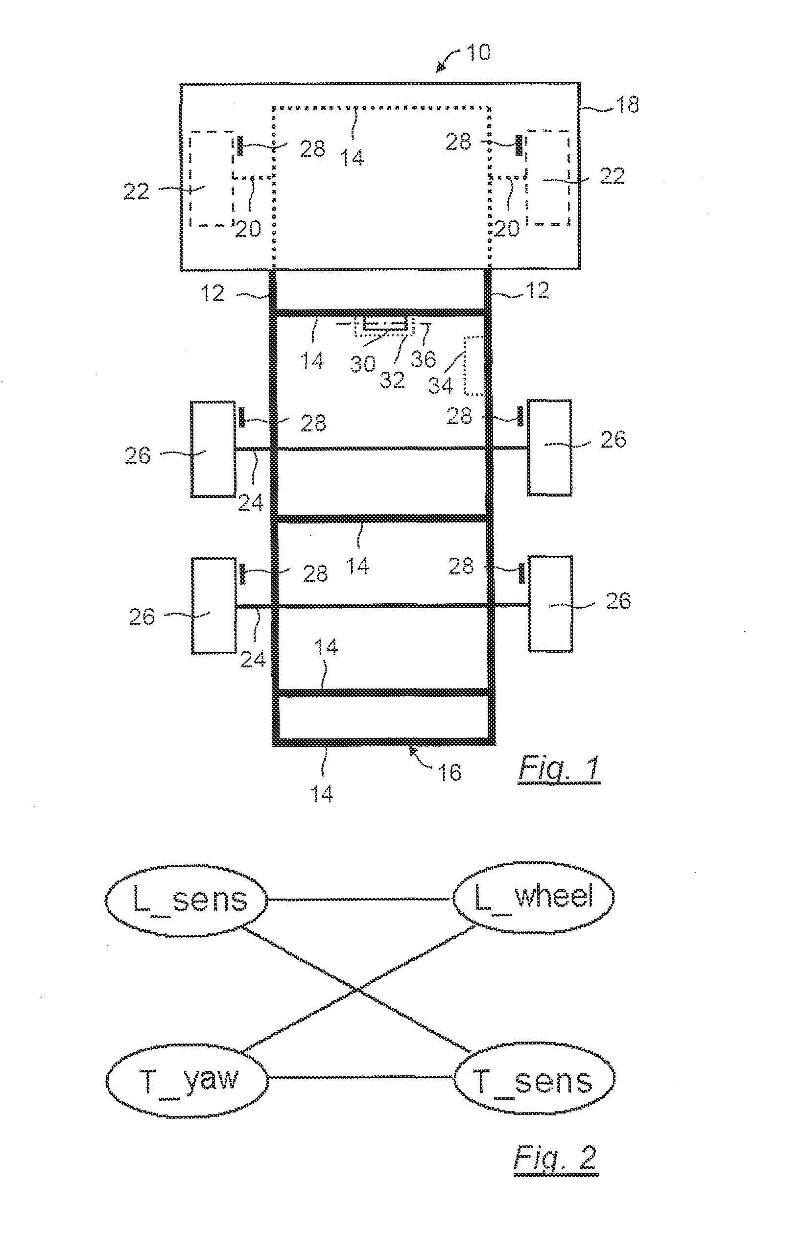
[0057]FIG. 1 is a simplified schematic plan view of a vehicle 10, which is preferably a utility vehicle, and, in the exemplary embodiment, a tractive unit. Vehicle 10 has a plurality of longitudinal beams 12 and a plurality of transverse beams 14, which together form a frame 16. The frame 16 supports vehicle body structures, in particular the driver's cab 18. In addition, the axles 20 of the front wheels 22 and one or more rear axles 24 with rear wheels 26 are also arranged at least indirectly.

[0058]The vehicle 10 has a vehicle movement dynamics control system. This is a driving assistance system that, through selective braking of individual front wheels 22 or rear wheels 26, counteracts any veering off of the vehicle 10. Through selective braking of individual wheels of these wheels 22, 26, the vehicle movement dynamics control system attempts to prevent the vehicle 10 from skidding. For this purpose, a steering angle sensor is provided that detects a steering angle request of the ...


PUM


Abstract

A method and device are provided for determining the installation position of a sensor module in a vehicle—namely, for determining whether the sensor module has its longitudinal axis oriented longitudinally or transversely. The sensor module has a longitudinal acceleration sensor for measuring a longitudinal module acceleration in the direction of the longitudinal axis and/or a transverse acceleration sensor for measuring a transverse module acceleration transversely with respect to the longitudinal axis. To this end, while the vehicle is travelling, a measured longitudinal module acceleration and/or a measured transverse module acceleration is compared with a longitudinal vehicle acceleration and/or a transverse vehicle acceleration ascertained in another way. By the comparison, at least one degree of conformity is ascertained, which represents the conformity of a measured module acceleration with a calculated vehicle acceleration. The installation position of the sensor module is then determined by means of the degree of conformity.

Description

FIELD OF THE INVENTION[0001]The present invention generally relates to a method and device for determining the installation position of a sensor module in a vehicle.BACKGROUND OF THE INVENTION[0002]DE 100 02 685 A1 and EP 1 578 651 BI disclose systems by which faulty installation of sensors in a vehicle can be detected. Applicant's DE 100 02 685 A1 is based, for example, on the idea that a yaw angle speed sensor is installed rotated through 180° with respect to the desired angular position, that is, for example, inverted. Incorrect installation of this kind leads to implausible values of the yaw angle speed signal, which is output, and can therefore be detected.[0003]EP 1 578 651 BI is also based on the idea that sensors are incorrectly installed despite mechanical coding, and is therefore aimed at checking the installation position of a sensor during operation.SUMMARY OF THE INVENTION[0004]Generally speaking, it is an object of the present invention to improve the determination of ...

Claims


Application Information

Patent Timeline
Patent Type & Authority Applications(United States)
IPC IPC(8): G01P21/00
CPCG01P21/00B60T2270/406B60T8/885B60T2201/16
Inventor KOPPER, HEIKOMICHAELSEN, ARNEMUNKO, TOBIAS
Owner ZF CV SYST EURO BV
Why Eureka
Try Eureka