Refrigeration cycle device, equipment, and refrigeration cycle method

a technology of refrigeration cycle and refrigeration cycle, which is applied in the direction of cooling fluid circulation, domestic cooling apparatus, lighting and heating apparatus, etc., can solve the problem of insufficient lubricating oil in the compressor, and achieve the effect of stable operation and stably returning

Active Publication Date: 2014-11-13
MITSUBISHI ELECTRIC CORP
View PDF6 Cites 20 Cited by
  • Summary
  • Abstract
  • Description
  • Claims
  • Application Information

AI Technical Summary

Benefits of technology

[0014]Since the refrigeration cycle device, equipment, and refrigeration cycle method of the present disclosure include the conveying device which conveys out the fluid mixture containing the liquid refrigerant and the lubricating oil retain

Problems solved by technology

If the fluid mixture is left to stand, the lubrica

Method used


Image

  • Refrigeration cycle device, equipment, and refrigeration cycle method
  • Refrigeration cycle device, equipment, and refrigeration cycle method
  • Refrigeration cycle device, equipment, and refrigeration cycle method

Examples


embodiment 1

[0025]An air-conditioning device 10 provided with a refrigeration cycle device 100 of Embodiments of the disclosure will now be described with reference to FIGS. 1 to 4.

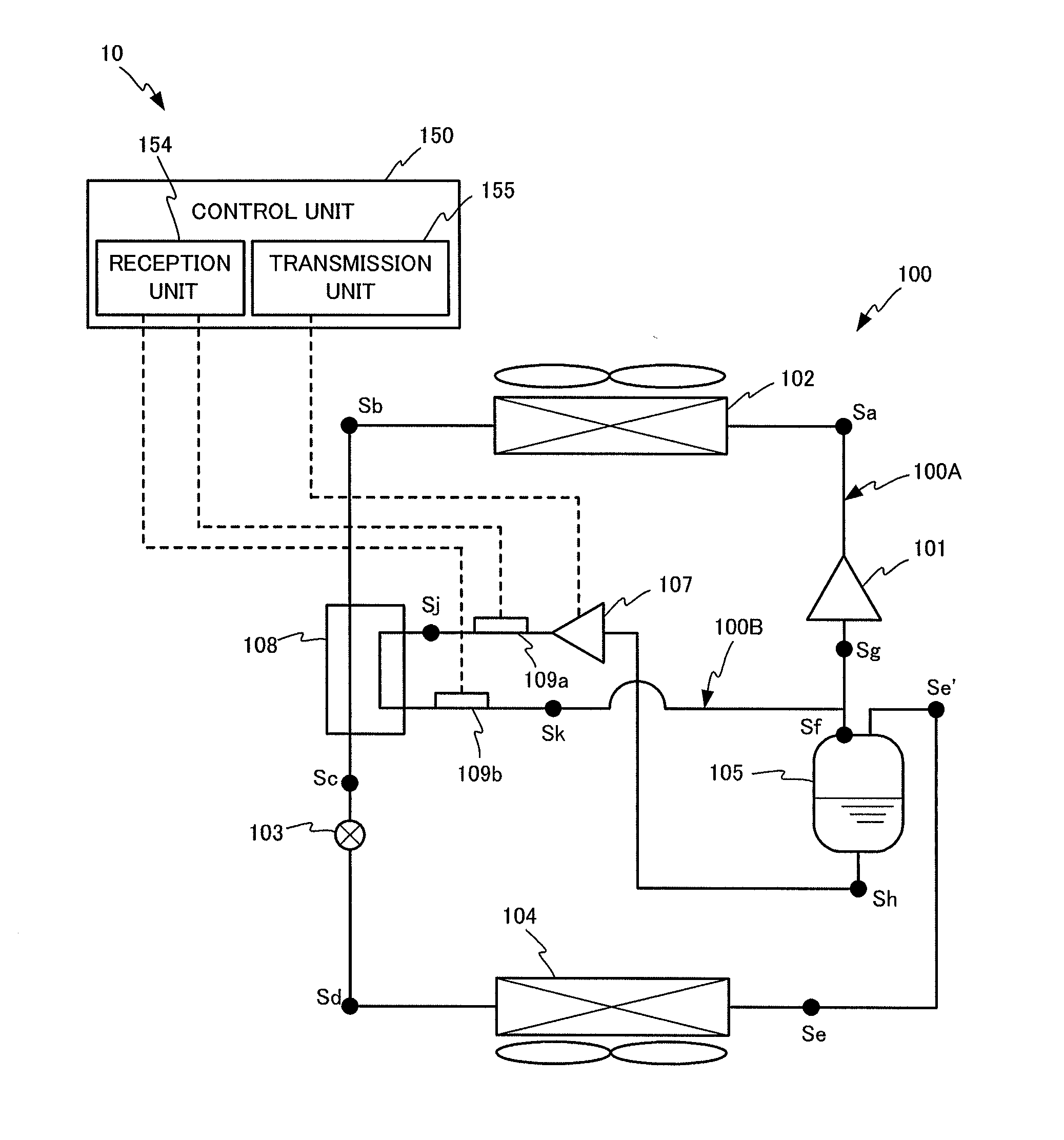
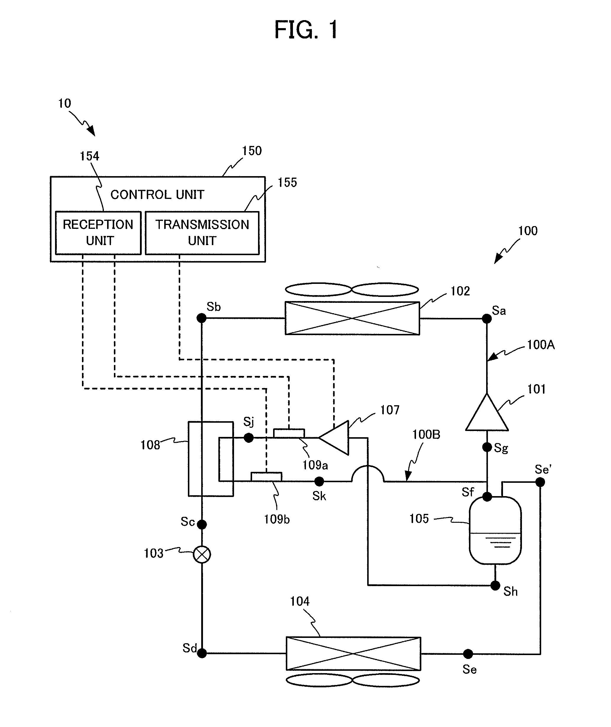
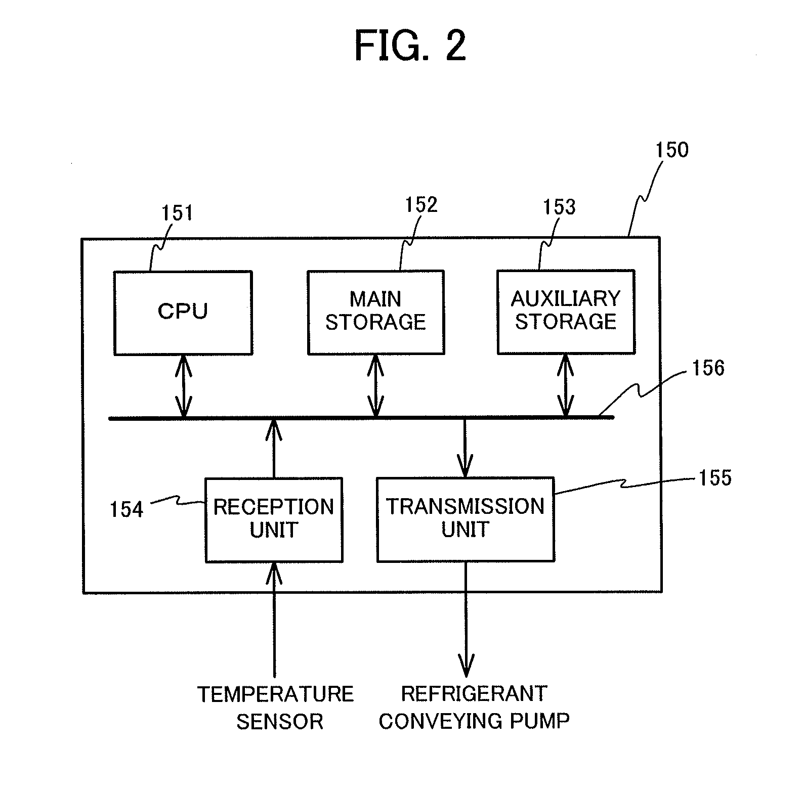
[0026]The air-conditioning device 10 of the Embodiment supplies cool air or warm air, and, as illustrated in FIG. 1, is provided with the refrigeration cycle device 100 including a main circuit 100A and a bypass circuit 100B, and a control unit 150 which controls the refrigeration cycle device 100.

[0027]The main circuit 100A of the refrigeration cycle device 100 refluxes refrigerant, as well as generates cool air and warm air by absorption and release of heat accompanied by phase change of the refrigerant, and is provided with a compressor 101, a condenser 102, an expansion valve 103, an evaporator 104, a refrigerant-storing container (accumulator) 105, and a pipe-shaped flow channel which connects all of the above portions.

[0028]The compressor 101 comprises, for example, a scroll compressor and a screw compressor, a...

embodiment 2

[0070]Although, in the Embodiment 1, the pump is illustrated as a constitution in which the fluid mixture of the liquid refrigerant and the lubricating oil is conveyed out from the refrigerant-storing container, any constitution is optional as long as the constitution is a conveying device which can stably convey out the fluid mixture. Embodiment 2 in which an ejector is used as the conveying device will now be described by using FIGS. 5 to 8. The same reference signs are used for the same or similar constitution in Embodiment 1. An air-conditioning device 20 according to the present Embodiment is different from the air-conditioning device 10 according to Embodiment 1 in that the air-conditioning device 20 comprises an ejector 250 in place of the refrigerant conveying pump 107.

[0071]As illustrated in FIG. 5, the air-conditioning device 20 comprises a refrigeration cycle device 200 including a main circuit 200A and a bypass circuit 200B, and a control unit 150 which controls the refr...

embodiment 3

[0103]Next, an air-conditioning device 30 of Embodiment 3 of the present disclosure will be described by using FIG. 9. The same reference signs are used for the same or similar constitution in the above Embodiments, and the description thereof is omitted or simplified. The air-conditioning device 30 according to the Embodiment is different from the air-conditioning device 10 according to Embodiment 1 in that the air-conditioning device 30 is provided with an expander 301 in place of the conveying pump 107 or the like.

[0104]As illustrated in FIG. 9, the air-conditioning device 30 comprises a refrigeration cycle device 300 including a main circuit 300A and a bypass circuit 300B, and a control unit 150 which controls the refrigeration cycle device 300.

[0105]The main circuit 300A comprises the compressor 101, the condenser 102, the expansion valve 103, the evaporator 104, the refrigerant-storing container 105 (accumulator), and the pressure sensor 201 which are described in Embodiment 1...


PUM


Abstract

A refrigeration cycle device includes: a compressor that constitutes a refrigeration cycle and compresses a supplied refrigerant; a refrigerant-retaining container that retains the refrigerant into which lubricating oil for the compressor is mixed, and which separates the gas refrigerant from the liquid refrigerant, and sends out the gas refrigerant to the compressor; a refrigerant conveying pump that conveys a fluid mixture including the liquid refrigerant and the lubricating oil retained in the refrigerant-retaining container; and an internal heat exchanger that changes the liquid refrigerant conveyed out from the refrigerant-retaining container by the refrigerant conveying pump to the gas refrigerant, and provides the compressor with the gas refrigerant together with the lubricating oil. Since the refrigerant conveying pump conveys the fluid mixture containing the liquid refrigerant and the lubricating oil retained in a refrigerant-retaining container, stable operation is possible.

Description

TECHNICAL FIELD [0001]The present disclosure relates to a refrigeration cycle device, equipment, and a refrigeration cycle method.BACKGROUND ART [0002]The refrigeration cycle device generates cool air or the like by utilizing absorption and release of heat when a circulating refrigerant changes its phase from gas to liquid or from liquid to gas. Patent Literature 1 discloses an example of such refrigeration cycle device.[0003]A refrigeration cycle device described in Patent Literature 1 below is provided with an accumulator (refrigerant-storing container, gas-liquid separator) which temporarily stores a refrigerant and which at the same time separates the gas refrigerant from the liquid refrigerant, and returns only the gas refrigerant to a compressor. The accumulator stores a fluid mixture of lubricating oil and the liquid refrigerant which has been discharged from the compressor and which has been refluxed back in a refrigerant circuit. If the fluid mixture is left to stand, the l...

Claims


Application Information

Patent Timeline
IPC IPC(8): F25B43/02F25B49/02
CPCF25B43/02F25B49/02F25B11/00F25B2341/0012F25B2400/13F25B2400/23F25B2600/2515F25B2700/1933F25B2700/2103F25B31/004F25B1/00
Inventor HIGASHIIUE, SHINYA
Owner MITSUBISHI ELECTRIC CORP
Why Eureka
Try Eureka