Rotary parlour arranged to house animals to be milked

Active Publication Date: 2014-11-13
DELAVAL HLDG AB
16 Cites 20 Cited by

AI-Extracted Technical Summary

Problems solved by technology

It is here a risk that the robot arm comes in contact with a rear leg of the cow.
In this case, it is...

Benefits of technology

[0004]The object of the present invention is to provide a rotary parlour, where a robot arm has to extend past at least one portion of the animal...

Abstract

A rotary parlour arranged to house animals to be milked includes an annular rotary platform (1), at least one milking stall (3) defined by at least one side wall element (2) and a storing device (8) adapted to hold teat cups (9) in a parking position, and a restricting element (8a, 13a, 16a) adapted to restrict the mobility of the animal (4) in the milking stall in a manner such that a free space (12) is created between the animal (4) and a side wall element (2) in a part of the milking stall (3), where the free space (12) is used by a robot arm (10) when fetching a teat cup in the storing device to attach to a teat of the animal (4) in the milking stall (3).

Application Domain

CathetersAnimal housing

Technology Topic

ParlourEngineering +2

Image

  • Rotary parlour arranged to house animals to be milked
  • Rotary parlour arranged to house animals to be milked
  • Rotary parlour arranged to house animals to be milked

Examples

  • Experimental program(1)

Example

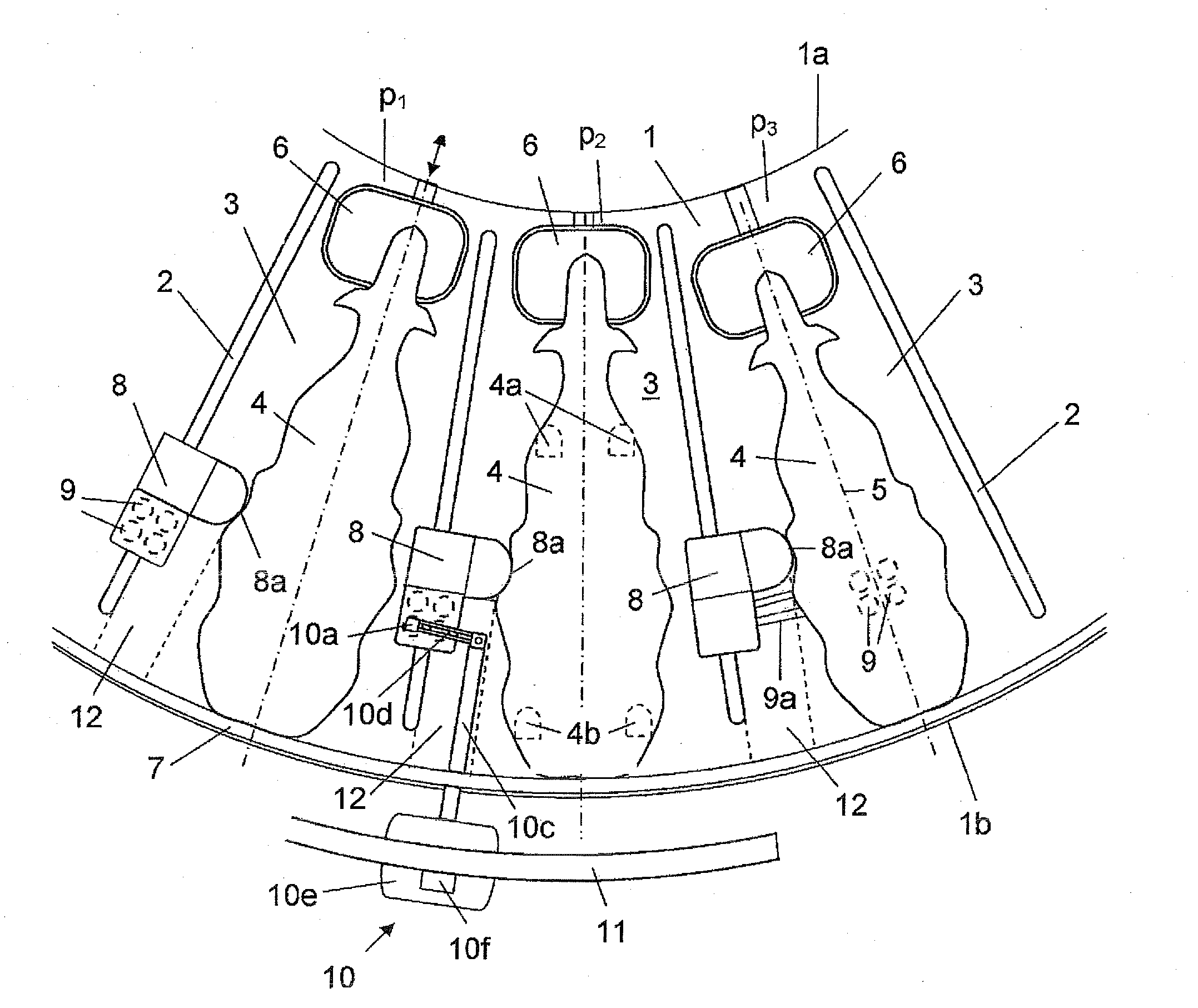
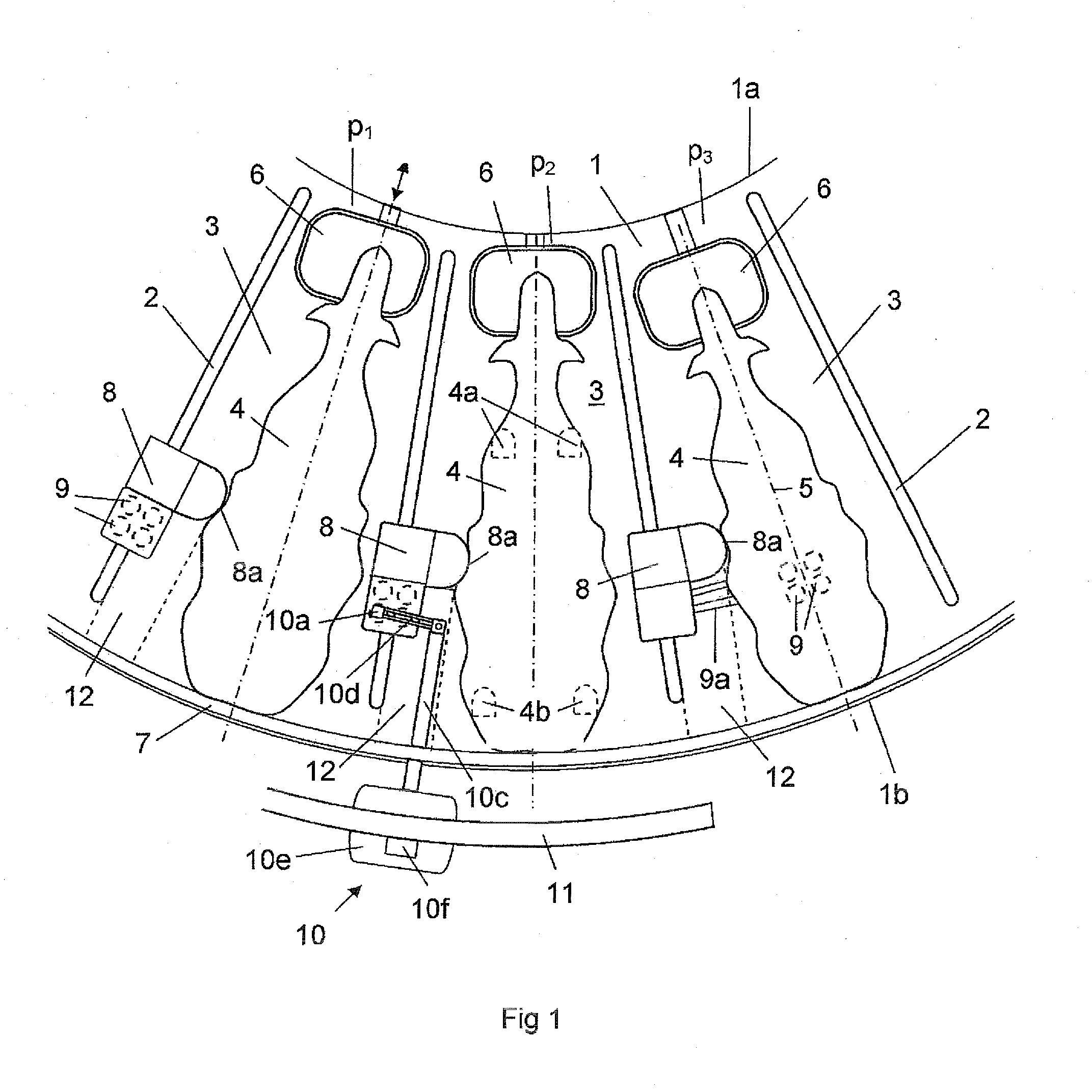
[0025]FIG. 1 shows a part of an annular rotary platform 1. The platform 1 is provided with a plurality of side wall elements 2 each having a substantially radial extension on the platform 1. The side wall elements 2 divide the annular platform into a plurality of milking stalls. FIG. 1 shows three of the milking stalls 3 on the rotary platform 1. A cow 4 is standing in the respective milking stall 3. The positions of the front legs 4a and the rear legs 4b of the cow 4 in one of the milking stalls 3 are indicated. The cows 4 are here standing in a substantially radial direction on the annular platform 1 with the heads at the vicinity of a radial inner edge portion 1 a of the platform 1. The longitudinal axes 5 through the cows 4 are indicated.
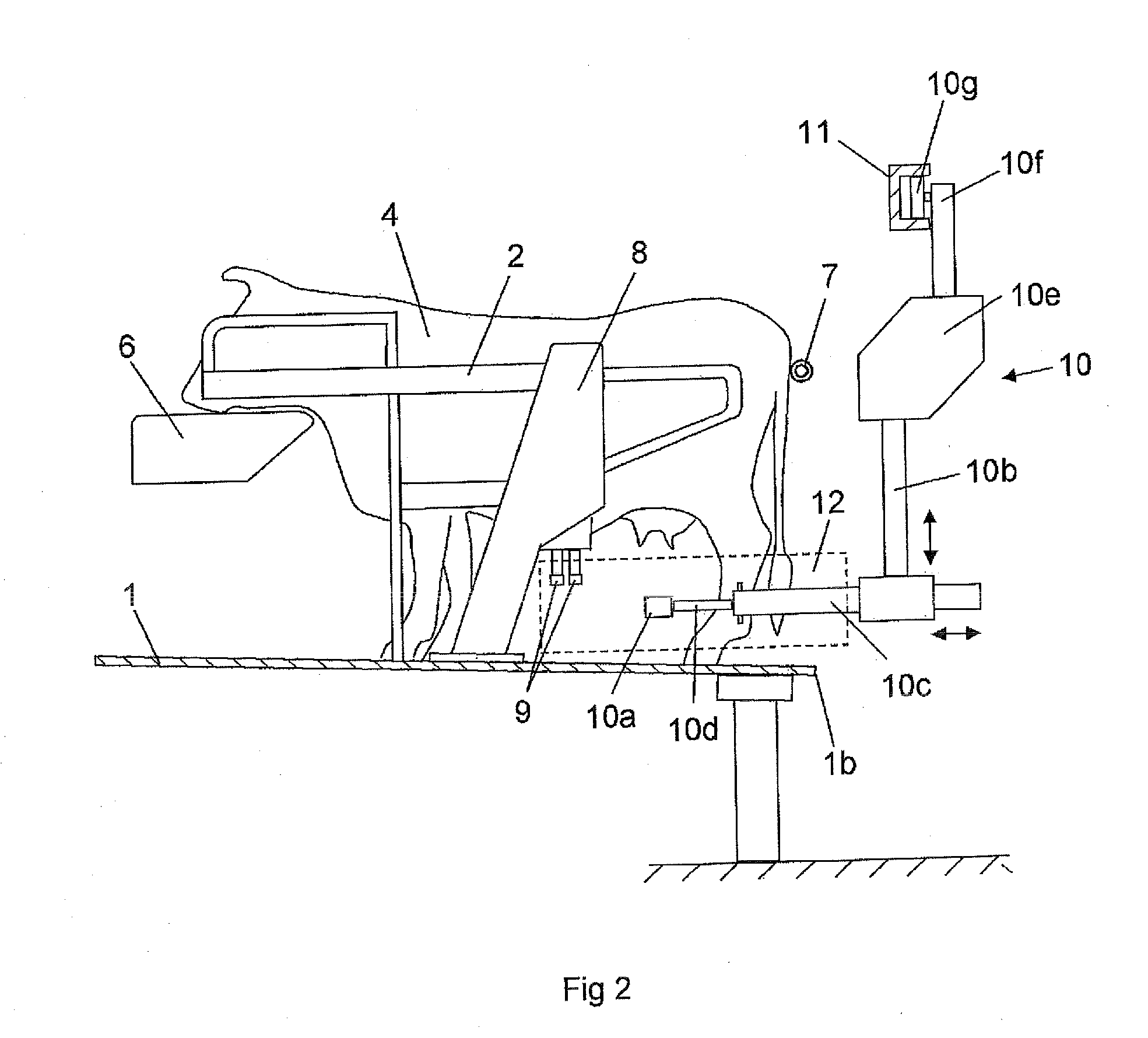
[0026]Each milking stall 3 comprises a movably arranged feeding trough 6. A rump rail 7 is arranged at a distance above a radial outer edge portion 1b of the platform 1. The rump rail 7 is adapted to define the positions of the rear portions of the cows 4 in the milking stalls 3. Each milking stall 3 also comprises a storing device 8 adapted to store teat cups 9 to be used in the milking stall 3. The storing devices 8 with the teat cups 9 are, in this case, arranged on the left side of the cow 4 in the respective milking stalls 3. FIG. 2 shows one of the milking stalls 3 on the platform 1 from the side. The storing device 8 have a cabinet-like structure and it constitutes a part of a side wall element 2. The storing device 8 is mounted on a floor surface 1c of the platform 1. The storing device 8 holds four teat cups 9 in a parking position at a distance above the platform 1 on the left side of the cow 4. The parked teat cups 9 are positioned in front of the rear legs 4b and behind the front legs 4a of the cow 4 in the milking stall 3. The teat cups 9 are parked relatively close to the teats of the cow 4. Such a positioning of the storing device 8 results in a short pull out length of the milk tubes 9a when the teat cups 9 are attached to the teats of a cow 4 in the milking stall 3. Furthermore, the risk that the milk tubes 9a become entangled with each other during the milking process and a retracting process is relatively low.
[0027]A milking robot arm 10 is adapted to attach the teat cups 9 to the teats of the cow 4. The robot arm 10 comprises a gripping member 10a adapted to grip the parked teat cups 9 in the storing device and attach them to the teats of a cow 4. The robot arm 10 also comprises positioning means adapted to move the gripping member 10a to desired positions. The positioning means of the robot arm 10 comprises a first positioning element 10b adapted to adjust the position of the gripping member 10a in a vertical direction, a second positioning element 10c adapted to adjust the position of the gripping member 10a along a straight line path in a horizontal plane and a third positioning element 10d adapted to adjust the position of the grip member 10a in a horizontal plane by means of a pivoting motion. Furthermore, the robot arm 10 comprises a body 10e and a suspension device 10f by which the robot arm 10 is suspended in an overhead rail member 11. The rail member 11 has a curved extension substantially vertically above the radially outer edge portion 1b of the 1 platform 1. The suspension device 10f comprises rollers 10g or the like by which the robot arm 10 is movably arranged along the rail member 11.
[0028]Each milking stalls 3 comprises restricting means adapted to restrict the mobility of the cow in the milking stall 3 in a manner such that a free space 12 is created between the cow 4 and the left side wall element 2 in a predetermined part of the milking stall 3. Said predetermined part of the milking stall 3 is, in this case, located between an outer edge portion 1b of the platform and the storing device 8. The free space 12 is indicated with doted lines in the figures. In the embodiment shown in FIG. 1, the restricting means comprises a contact surface 8a of the storing device 8. The storing device 8 has here a design with a protruding portion comprising said contact surface 8a The contact surface 8a is located at a predetermined distance from the side wall element 2. The contact surface 8a is adapted to come in contact with a side portion of the cow 4. The contact surface 8a prevents that the cow 4 comes too close the left side wall element 2. The contact surface 8a ensures that the cow 4 will be positioned at at least a predetermined distance from the side wall element 2. Said distance constitutes the width of the free space 12. The free space 12 may have a height corresponding to the height of the legs of the cows 4.
[0029]During operation of the rotary parlour, a cow 4 to be milked enters a milking stall 3 at the first rotation position p1. The feeding trough 6 is adjusted to a position such that it moves the cow 4 to a position in which an end portion of the cow 4 comes in contact with the rump rail 7. Thereby, the movably arranged feeding trough 6 defines a milking position of the cow 4 in a longitudinal direction in the milking stall 3. The rear legs 4b of the cow 4 are here in a position relatively close to radially outer edge portion 1b of the platform 1. The contact surface 8a of the storing device 8 ensures that no part of the cow 4 occupies said free space 12.
[0030]The robot arm 10 may be located in a resting position outside the radially outer edge portion 1b of the platform 1. The robot arm 10 is moved from the resting position when the milking stall 3 reaches a second rotation p2. Initially, the first positioning element 10b of the robot arm 10 may be activated in order to adjust the position of the gripping member 10a to a suitable vertical level above the floor surface 1c of the platform. The second positioning element 10c moves then the gripping member 10a along a straight line path into the free space 12. The gripping member 10a is here moved through a space between the left side wall element 2 and the left rear leg of the cow 4. The gripping member 10a is moved to a position on the platform 1 in the vicinity of the storing device 8.
[0031]The third positioning element 10d performs then a pivoting motion of the gripping member 10a to a gripping position, in which the gripping member 10a is able to grip a teat cup 9 in the storing device 8. FIG. 1 shows the gripping member 10a in the gripping position. As soon as the gripping device 1 has gripped a teat cup 2 in the storing device 11, the third positioning element 10d performs a pivoting motion of the gripping member 10a in a direction such the gripping member 10a is moved from the storing device 8 to a position below the udder of the cow 4. The gripping member 10a and the teat cup 9 are moved to this position via a space between a front leg 4a and a rear leg 4b of the cow 4.
[0032]Finally, the first positioning element 9b moves the gripping member upwards to an attaching position in which the teat cup 9 is attached to a teat of the cow 4. During this gripping and attaching process of the teat cup 9, the whole robot arm 1 can be moved along the curved rail member 11 with the same velocity as the platform 1. Thereby, it is possible to avoid mutual motions between the robot arm 10 and the cow 4 on the rotary platform 1. The milking robot 10 may fetch one teat cup 9 from the storing device 8 at a time. Alternatively, the milking robot 10 fetches more than one teat cup from the storing device 8 at a time. When all teat cups 9 have been attached to the teats of the cow 4, the robot arm 10 is retracted to the resting position outside the radial outer edge portion 10b of the platform 1.
[0033]The robot arm 10 uses the free space 12 at the left side wall element 2 during the whole attaching process of the teat cups 9. Due to the existence of said contact surface 8a, no portion of the cow 4, such as the left rear leg of the cow 4, are able to occupy said free space 12 during the attaching process of the teat cups 9. Thus, the robot arm 10 will not come in contact with any portion of the cow 4 in the free space 12 during the attaching process of the teat cups 9. Consequently, there is no risk that the cow 4 being injured by the robot arm 10 or the robot arm 10 being damaged by the cow 4 when the robot arm 10 extends past the rear legs 4b of the cow 4 during the attaching process of the teat cups 9. When the milking stall 3 reaches the third rotation position p3, the milking process of the cow 4 starts. As soon as the milking process of the cow 4 has been finished, a not shown retraction device in the storing device 8 is activated. The retraction device provides a pulling force in the respective milk conduits 9a of the teat cups 9 such that they are removed from the teats of the cow 4 and pulled back to the parking positions in the storing device 8.
[0034]FIG. 3 shows a alternative embodiment of the invention. In this case, two robot arms 10 are used for attaching the teat cups 9 to the teats of the cows 4 when the milking stall 3 is in the second rotational position p2. A first robot arm 10 fetches two teat cups 9 which are parked in a storing device 8 arranged on the left side of the cow 4 and attaches them to the left teats of the cow 4 in the milking stall 3. At substantially the same time, a second robot arm 10 fetches two teat cups 9 which are parked in a storing device 8 on the right side of the cow 4 and attaches them to the right teats of the cow 4. FIG. 3 shows the robot arms 10 in the attaching position. The robot arms 10 are retracted to a resting position outside the radial outer edge portion 1b of the platform 1 when the teat cups 9 have been attached to the teats of the cow 4.
[0035]In this case, each milking stall 3 comprises two movably arranged restricting elements 13. The restricting elements 13 are mounted on opposite sides of the milking stall 3 on a respective side wall element 2. The restricting elements 13 are movable between a non-active position in which they substantially do not restrict the mobility of the cow 4 in the milking stall 3 and an active position in which they restrict the mobility of the cow 4 in a transverse direction in the milking stall 3 such that free spaces 12 are created on both sides of the cow 4. The movably arranged restricting elements 13 comprise a contact surface 13a adapted to come in contact with a side portion of the cow 4 at a predetermined distance from the side wall element 2. The restricting elements 13 are movably arranged by means of power members 14. The power members 14 may, for example, be hydraulic cylinders or pneumatic cylinders. A schematically disclosed control unit 15 controls the power members 14.
[0036]During operation of the rotary parlour, a cow 4 to be milked enters the milking stall 3 in the first rotation position p1. The restricting elements 13 are here in the non-active position such they do not restrict the mobility of the cow 4 when it enters the platform 1. The feeding trough 6 is adjusted to a position such that it moves the cow 4 in the longitudinal direction to a position in which an end portion of the cow 4 comes in contact with the rump rail 7. When the milking stall 3 reaches the second rotation position p2, the control unit 15 activates the power members 14 such they move the restricting elements 13 from the non-active position to the active position. The contact surfaces 13a of the restricting elements 13 moves to a position at a predetermined distance from the respective side wall elements 2. Thereby, the cow 4 will be positioned in the milking stall 3 at at least said predetermined distance from the respective side wall elements 2. Free spaces 12 are here created on both sides of the cow 4. A first free space 12 is created at the left side wall element 2 of the milking stall 3 and a second free space is created at the right side wall element 2 of the milking stall 3.
[0037]The robot arms 10 are located in a resting position substantially radially outside the respective free space 12 when the milking stall 3 reaches the second rotation position p2. The second positioning elements 10c of each robot arm 10 moves the gripping members 10a along a straight line path into the respective free spaces 12. One robot arm 10 is moved through a space between the left wall element 2 and the left rear leg 4b of the cow 4 and the other robot arm 10 is moved through a space between the right wall element 2 and the right rear leg 4b of the cow 4. The gripping members 10a of the robot arms 10 are moved to a position in the vicinity of the respective storing devices 8 in the milking stall 3.
[0038]Each third positioning element 10d of robot arms 10 performs a pivoting motion of the gripping members 10a to a gripping position, in which each gripping member 10 is able to grip a teat cup 9 in the respective storing devices 8. Each third positioning element 10d of the robot arm performs then a pivoting motion of the gripping member 10a in an opposite direction to a position below the udder of the cow 4. One gripping member 10a is moved to this position via a space between a left front leg 4a and a left rear leg 4b of the cow 4 and the other gripping member 10a is moved to this position via a space between a right front leg 4a and a right rear leg 4b of the cow 4. Finally, each first positioning element 10b of the robot arms 10 moves the gripping member 10a upwards to an attaching position in which the teat cup 9 is attached to a teat of the cow 4. Thereafter, each robot arm 10 fetches the remaining teat cup 9 in the respective storing devices 8 and attaches them to the remaining teats of the cow 4. When all teat cups 9 have been attached to the teats of the cow 4, the robot arms 10 are retracted to the resting positions outside the radial outer edge portion 1b of the platform 1. At the same time, the control unit 15 activates the power members 14 such the restricting elements 13 are moved from the active position to the non-active position. Thus, during the following milking process of the cow 4, it is possible for the cow 4 to perform motions in a transverse direction in the milking stall 3. In this case, the restricting elements 13 are only moved to the active position during the attachment process of the teat cups 9.
[0039]FIG. 4 shows a further alternative embodiment of the invention. In this case, each milking stalls 3 comprises a stationary restricting element arranged on a left side wall element 2 of the milking stall 3. The restricting element is here a bar element 16 having a contact surface 16a adapted to restrict the mobility of the cow 4 in the milking stall 3 in a manner such that a free space 12 is created at the left side wall element 2. Each milking stall 3 comprises a storing device 8 with teat cups 9 forming a part of left side wall element 2. The storing devices 8 are here arranged in the vicinity of the radial outer edge portion 1b of the platform 1.
[0040]During operation of the rotary parlour, a cow 4 to be milked enters a milking stall 3 in the first rotation position p1. The contact surfaces 16a of the bar element 16 ensures that the cow 4 will be positioned in the milking stall 3 at at least a predetermined distance from the left side wall element 2. Thus, a free space 12 is created between the cow 4 and said side wall element 2. FIG. 4 shows the robot arm 10 in a resting position. When the milking stall 3 reaches the second rotation position p2, robot arm 10 is activated. The gripping member 10a of the robot arm 10 grips a teat cup 9 in the storing device 8. The gripping member 10a and the teat cup 9 are moves through said free space 12 to a suitable position on the platform 1. Thereafter, the robot arm 10 moves the gripping member 10a with the teat cup to an attaching position via the space between the front leg 4a and the rear leg 4b of the cow 4. When the teat cup has been attached to a teat, the robot arm 10 fetches and attaches the remaining teat cups 9 to the teats of the cow 4 in a correspondingly manner.
[0041]The invention is not limited to the described embodiments but may be varied and modified freely within the scope of the claims.

PUM

no PUM

Description & Claims & Application Information

We can also present the details of the Description, Claims and Application information to help users get a comprehensive understanding of the technical details of the patent, such as background art, summary of invention, brief description of drawings, description of embodiments, and other original content. On the other hand, users can also determine the specific scope of protection of the technology through the list of claims; as well as understand the changes in the life cycle of the technology with the presentation of the patent timeline. Login to view more.

Similar technology patents

Venous Catheter Device Capable of Being Sealed

PendingUS20220168548A1smoothly entereliminate risk
Owner:ZHEJIANG BAIHUO HEALTH TECH CO LTD

Method, System, and Apparatus to Prevent Electrical or Thermal-Based Hazards in Conduits

InactiveUS20180286618A1eliminate riskhigh degree of structural integrity
Owner:MANAGEMENT SCI

Coupling Device for Media Conduits

InactiveUS20080014774A1eliminate riskcompensation for play
Owner:VOSS AUTOMOTIVE

Process for machining deep mounting hole of slewing bearing ring

ActiveCN110961668Aeliminate risklow manufacturing cost
Owner:WAFANGDIAN BEARING GRP STATE BEARING ENG TECH RES CENT CO LTD

Classification and recommendation of technical efficacy words

  • eliminate risk

Vehicle lamp

InactiveUS7021805B2wide illumination areaeliminate risk
Owner:KOITO MFG CO LTD

Stirred tank bioreactor

ActiveUS20090311776A1eliminate risk
Owner:MILLIPORE CORP

Meniscal repair systems and methods

ActiveUS20100106169A1eliminate risk
Owner:CAYENNE MEDICAL INC

Biodegradable medical devices with enhanced mechanical strength and pharmacological functions

ActiveUS20060264531A1eliminate riskeliminate wear
Owner:CARDINAL HEALTH SWITZERLAND 515 GMBH

Blade for wind-power generators

InactiveCN101151458Aeliminate risk
Owner:GAMESA INNOVATION & TECH SA
Why Eureka
Try Eureka