High performance pulse valve

a pulse valve, high-performance technology, applied in the field of pulse valves, can solve the problems of significant valve pressure loss, achieve the effects of increasing the reliability and performance of the valve, increasing the pressure pulse of compressed air, and increasing the flow of compressed air

Inactive Publication Date: 2014-11-13
ALSTOM TECH LTD
View PDF10 Cites 3 Cited by
  • Summary
  • Abstract
  • Description
  • Claims
  • Application Information

AI Technical Summary

Benefits of technology

[0003]The subject pulse valve arrangement enables increased compressed air flow, increased pressure pulses of compressed air and increased valve reliability and performance. The subject pulse valve arrangement provides for an increased cross section area dedicated to pressure medium ports with the remaining circular cylindrical portion wall significantly limited in size to reduce undesirable pressure loss. By reducing pressure loss, the subject pulse valve achieves higher pressure pulses of compressed air to filter bag elements enabling more filtration area cleaning per pulse per valve. Additionally, an increased cross sectional area dedicated to pressure medium ports for increased compressed air flow means less wall to plunger contact. Unexpectedly, less wall to plunger contact results in fewer plunger malfunctions caused by grit on wall surfaces, wall dents, plunger misalignment, and the like, contrary to prior teachings.

Problems solved by technology

However, the remaining wall of the circular cylindrical portion restricts compressed air flow causing significant valve pressure loss.

Method used


Image

  • High performance pulse valve
  • High performance pulse valve
  • High performance pulse valve

Examples


Embodiment Construction

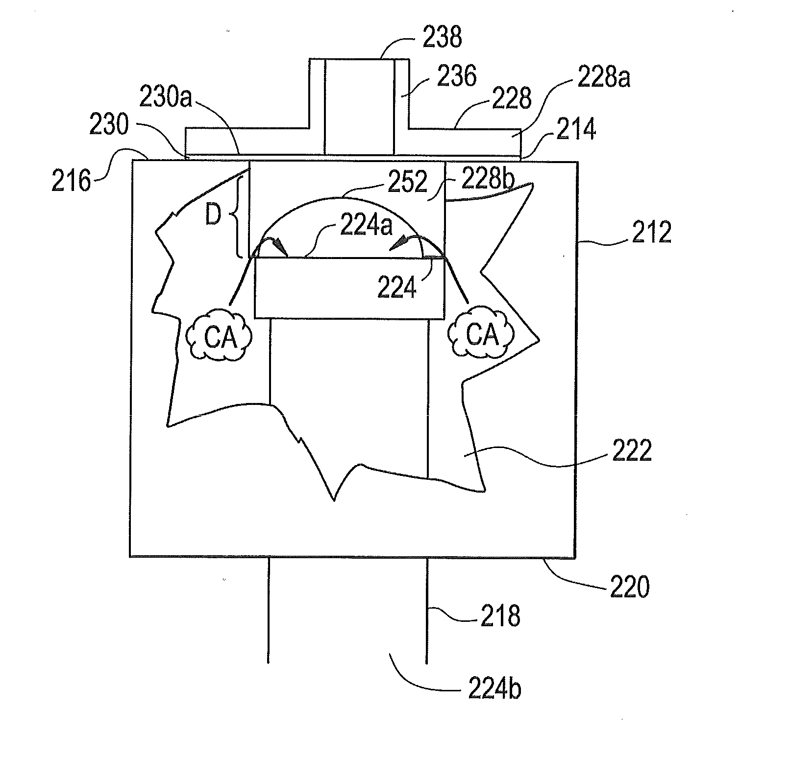
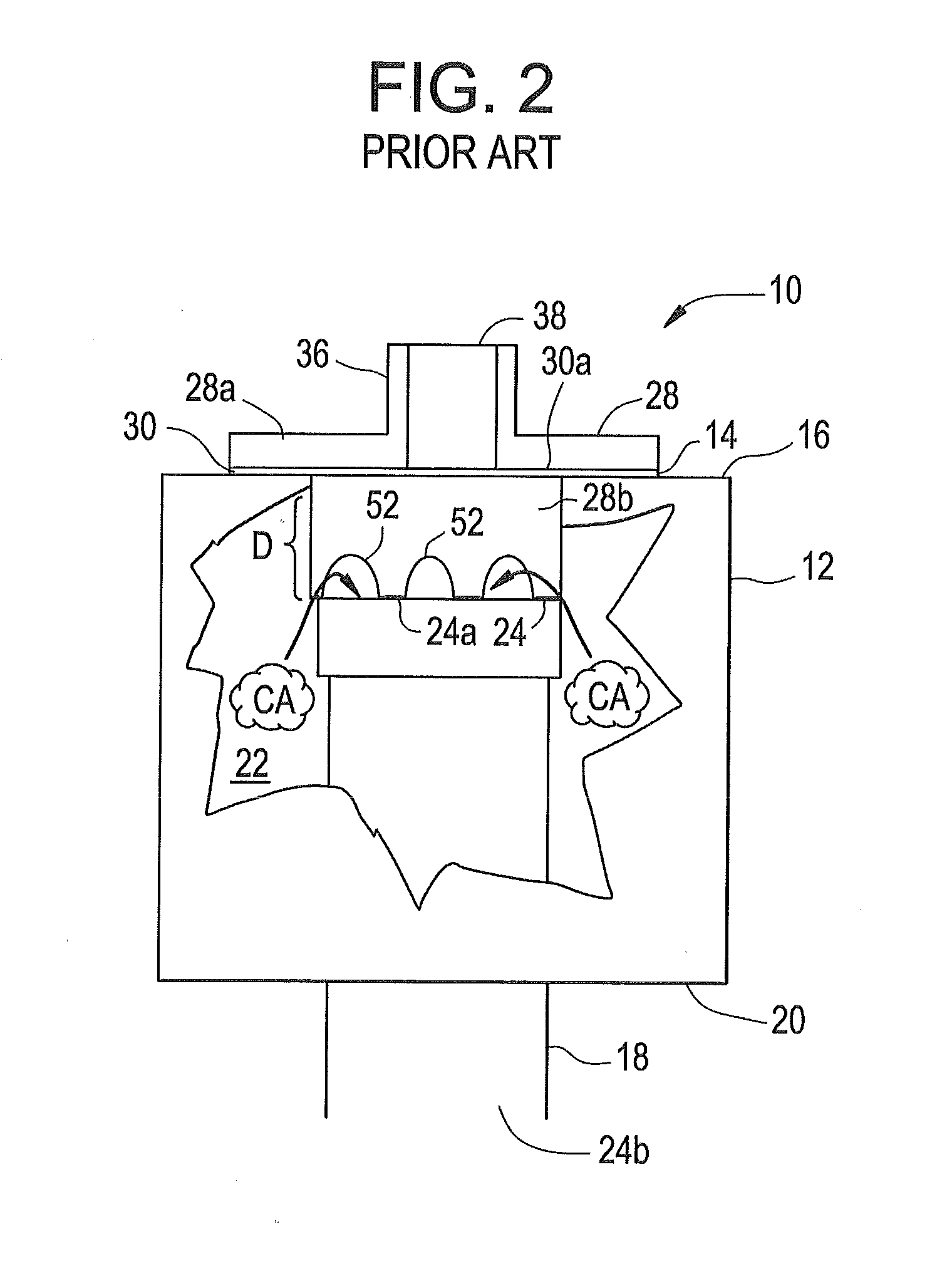
[0011]The prior art valve arrangement 10 illustrated in FIGS. 1 and 2 is used for delivering compressed-air “CA” pulses to vertically arranged, bag-shaped filter elements (not shown) in a filtering plant useful for cleaning polluted gases. The valve arrangement 10 is mounted in a pressure medium tank 12 through a circular opening 14 provided in the upper wall 16 of the tank 12. The tank 12 is a compressed air tank.

[0012]A vertical pressure tube 18 coaxial with opening 14, extends through the lower wall 20 and into interior area 22 of tank 12. An upper end 24 of pressure tube 18 is arranged a distance “D” below opening 14. The upper end 24 of the pressure tube 18 forms a valve seat 24a, and the lower end 24b of pressure tube 18 opens outside tank 12 fluidly connected to openings in the bag-shaped filter elements (not shown).

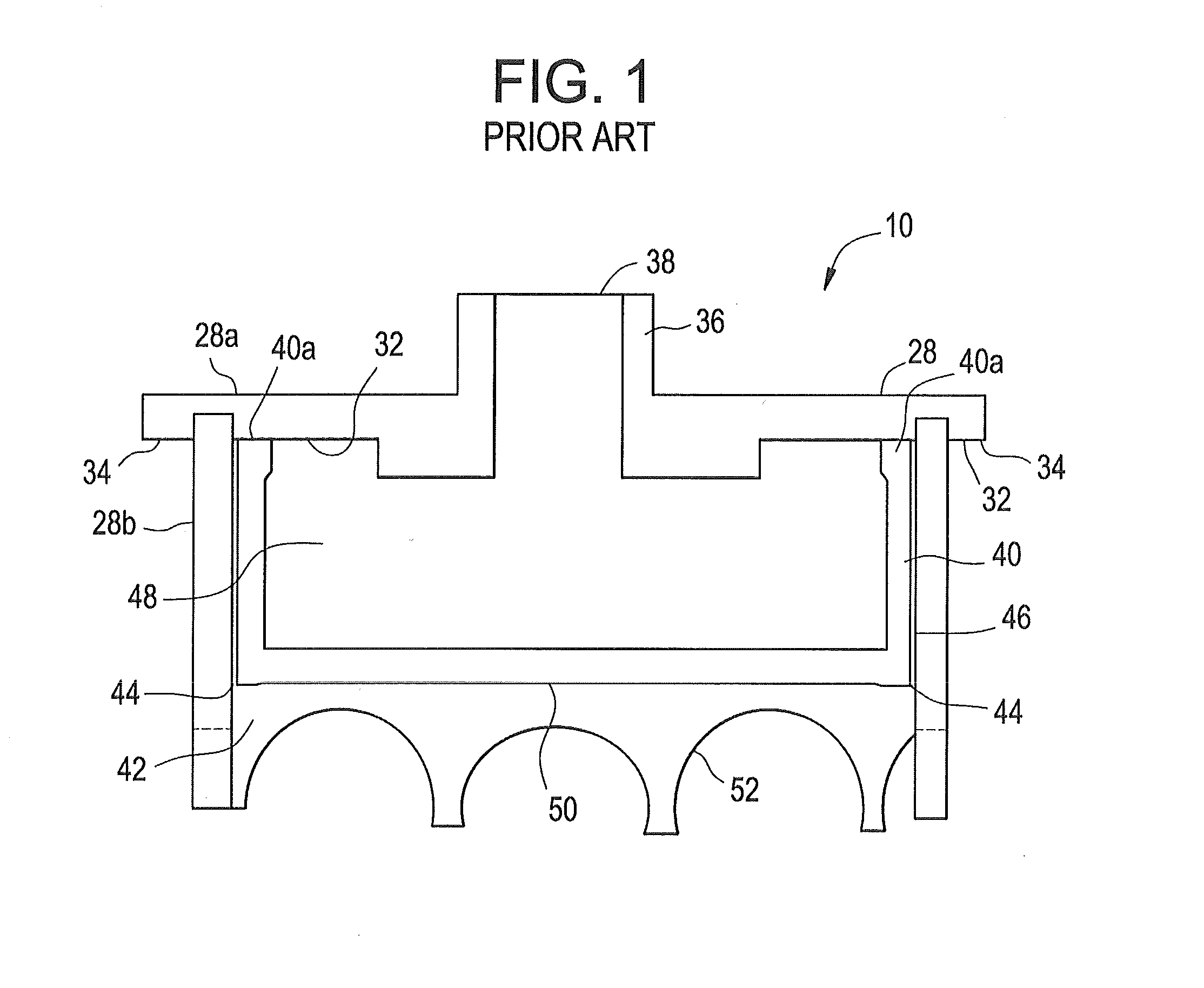
[0013]Valve arrangement 10 has a valve housing 28 consisting of two circular, coaxial parts, namely an upper part 28a and a tubular lower part 28b fixed together....


PUM

PropertyMeasurementUnit
interior areaaaaaaaaaaa
pressureaaaaaaaaaa
pressure dropaaaaaaaaaa

Abstract

A pulse valve arrangement includes a valve housing on which is fixed a control valve The valve housing includes a circular cylindrical portion with a valve member movably arranged therein. The valve chamber has an inlet adapted to be connected to a pressure medium source for allowing pressure medium to flow into the valve chamber and an outlet through which pressure medium flows out of the valve chamber. The control valve may be closed in which the outlet of the valve chamber is moved to a closing position blocking the flow of pressure medium, or may be opened in which the outlet of the valve chamber is moved to an opening position allowing a pulse of pressure medium therethrough. The valve member within the valve housing is freely displaceable within the circular cylindrical portion of the valve housing based on the pressure within the valve chamber as controlled by the control valve.

Description

FIELD OF THE INVENTION[0001]The present invention relates to a pulse valve. More particularly, the present invention relates to a pulse valve for higher pressure pulses of compressed air useful for cleaning filter elements in a filtering plant for cleaning polluted gases.BACKGROUND OF THE INVENTION[0002]A known valve arrangement disclosed in U.S. Pat. No. 5,533,706 incorporated herein in its entirety by reference, is used for delivering pulses of compressed air to filter elements, such as filter bags, in a filtering plant useful for cleaning polluted gases. The compressed air pulses are delivered to the interior of the filter elements to clean the elements by shaking and blowing loose dust cakes which, in the cleaning of polluted gases, attach to the walls of the filter elements. For this purpose of cleaning filter elements, the known valve arrangement is mounted on a compressed air tank. The valve arrangement includes a valve housing having a circular cylindrical portion forming a ...

Claims


Application Information

Patent Timeline
Patent Type & Authority Applications(United States)
IPC IPC(8): F16K31/12
CPCF16K31/12B01D46/04F16K3/246F16K27/041B01D46/71
Inventor HJELMBERG, ANDERS ERIK MARTINANDERSSON, RUNE STEN
Owner ALSTOM TECH LTD
Why Eureka
Try Eureka