Spectacles

a technology of rimless spectacles and rims, applied in the field of rimless spectacles, can solve the problems of glass material stiffness, glass material breakage, difficulty in drilling holes thereon, etc., and achieve the effect of enhancing the clipping force of the clipping member, reducing manufacturing difficulty, and enhancing manufacturing efficiency

Inactive Publication Date: 2014-11-13
SIU YU +1
View PDF7 Cites 37 Cited by
  • Summary
  • Abstract
  • Description
  • Claims
  • Application Information

AI Technical Summary

Benefits of technology

[0017]Another object of the present invention is to provide the spectacles, wherein it is not necessary to drill any hole on the lenses, so the difficulty in manufacturing is reduced and the manufacturing efficiency is thus increased.
[0018]Another object of the present invention is to provide the spectacles, wherein when a customer purchases the spectacles, he or she can receive the final product quickly due to special manufacturing and connection design of rimless spectacles in the present invention.
[0019]Another object of the present invention is to provide the spectacles, wherein the coupling slot of first connector comprises the coupling groove and the retention groove integrally formed at rear of the coupling groove, so that the clipping member of the second connector is able to securely retained in the retention groove when the connecting member of the second connector is inwardly slid into the coupling groove.
[0020]Another object of the present invention is to provide the spectacles, wherein the slanted surfaces inclinedly extended within the retention groove are able to prevent the clipping member accidentally and outwardly slid out of the coupling slot.
[0021]Another object of the present invention is to provide the spectacles, wherein the slanted surfaces of the retention slot are able to further be adapted for the clipping member biasing against the slanted surfaces for enhancing the clipping force of the clipping member, so as to securely coupling the first connector with the second connector.
[0022]Another object of the present invention is to provide the spectacles, which provides a coupling method for the easily connecting the bridge and / or temple units with the respective lenses without precisely complicated drilling or grinding lenses processes. Therefore, there is no need to grind the lenses to a precise shape or angle in order to match the coupling groove at the inner edge of the frame of the rims as mentioned above.

Problems solved by technology

In other words, the surface of the lens of either near-sighted or farsighted spectacles is not a flat surface, and the difficulty of drilling holes thereon is thus increased.
In addition, the stiffness of glass materials is high and drilling holes thereon is likely to cause the glass material to break.
If the hole is too big, the lens will be unstable after the temples and the bridge are mounted thereto.
If the hole is too small, the temples and the bridge cannot be affixed thereto.
Or the lens will be cracked when the temples and the bridge are forced to affix to the lens.
With the difficulty in drilling holes on the lens mention above, it is inconvenient for customers to purchase rimless spectacles because when one chooses his or her own rimless spectacles, the lenses and the spectacle frame are separately chosen by the customer and put together by a technician.
Because of the difficulty in drilling holes on an uneven lens surface, the technician usually takes longer time to put the lenses and the spectacle frame together.
In other words, the customer has to wait for a long time from choosing the spectacles to actually receiving the final product.
However, such rimless spectacles can be made only in particular styles of lenses and the assembling operation is relatively complicated.
However, the lens, especially the optical lens, is the most expensive part of the spectacles, so that the wear may not be able to afford having multiple spectacles.
However, the clipping connector may outwardly slide out of the coupling slot through the opening by accident.
Another main concern of traditional coupling method between the frame, including the bridge and / or the temples, and the lenses is that the lenses has to be precisely grinded to a shape and size exactly matching the connectors at the bridge or the temples for coupling therewith, so that the complicated drilling or grinding lenses process is time consuming and increase the cost the spectacles.
If the lenses did not be grinded to the predetermined coupling angle and shape, an undesired reflection is generated from the outer peripheral edge of the lens at the connection between each of the lenses and the rim frames.
Especially for those more sophisticated spectacles, those unwanted reflections will dramatically reduce the aesthetic feeling of the spectacles.
Therefore, if there is any tiny mistake occurred during the grinding process of the lenses, the failed lenses lead the spectacles manufactures or makers have no choice but throw away those expensive lenses away.

Method used


Image

  • Spectacles
  • Spectacles
  • Spectacles

Examples


fifth embodiment

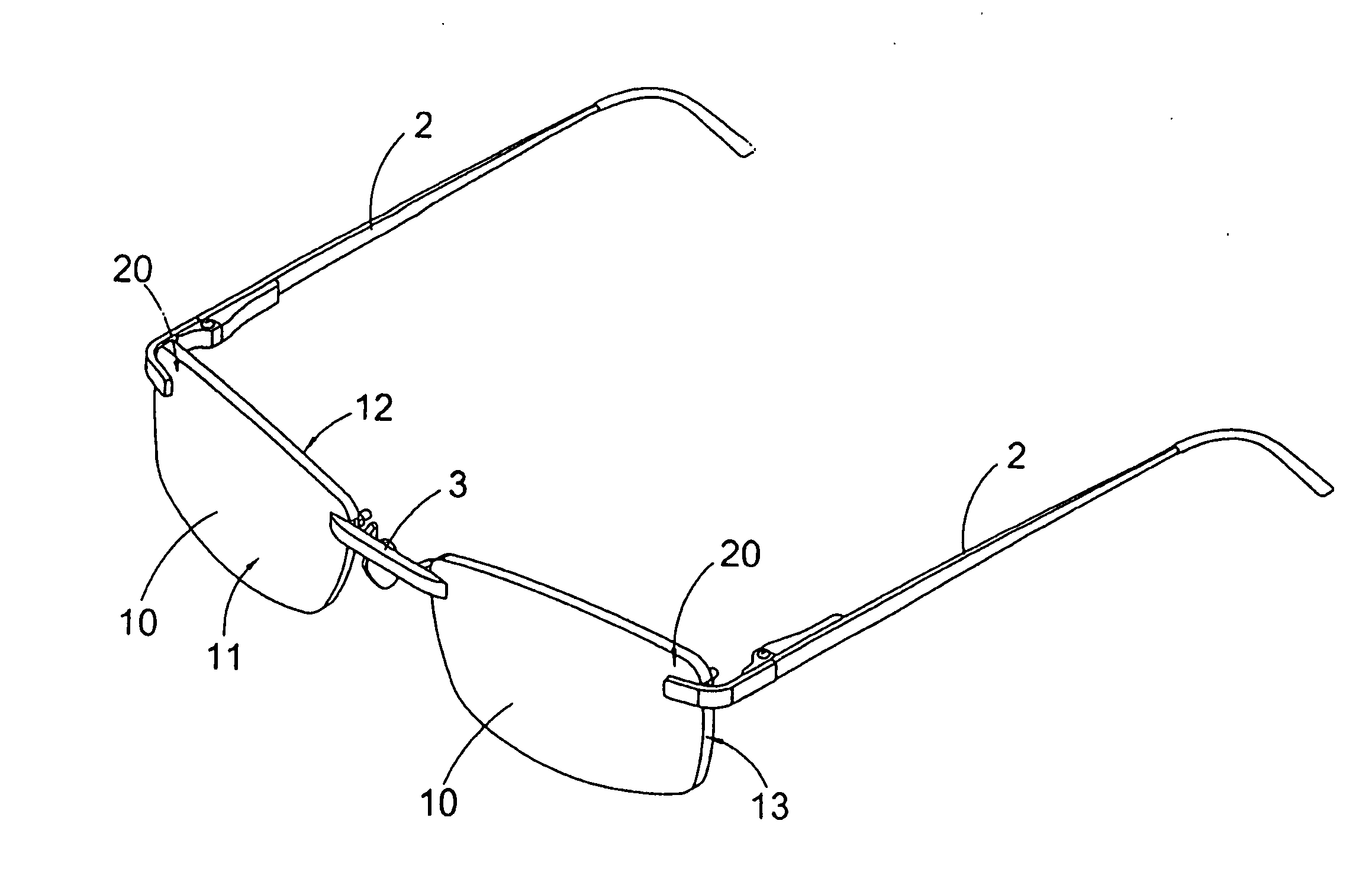
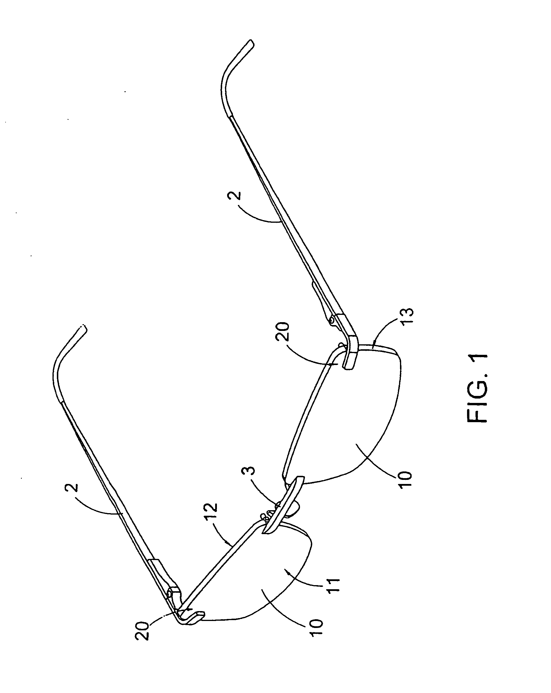
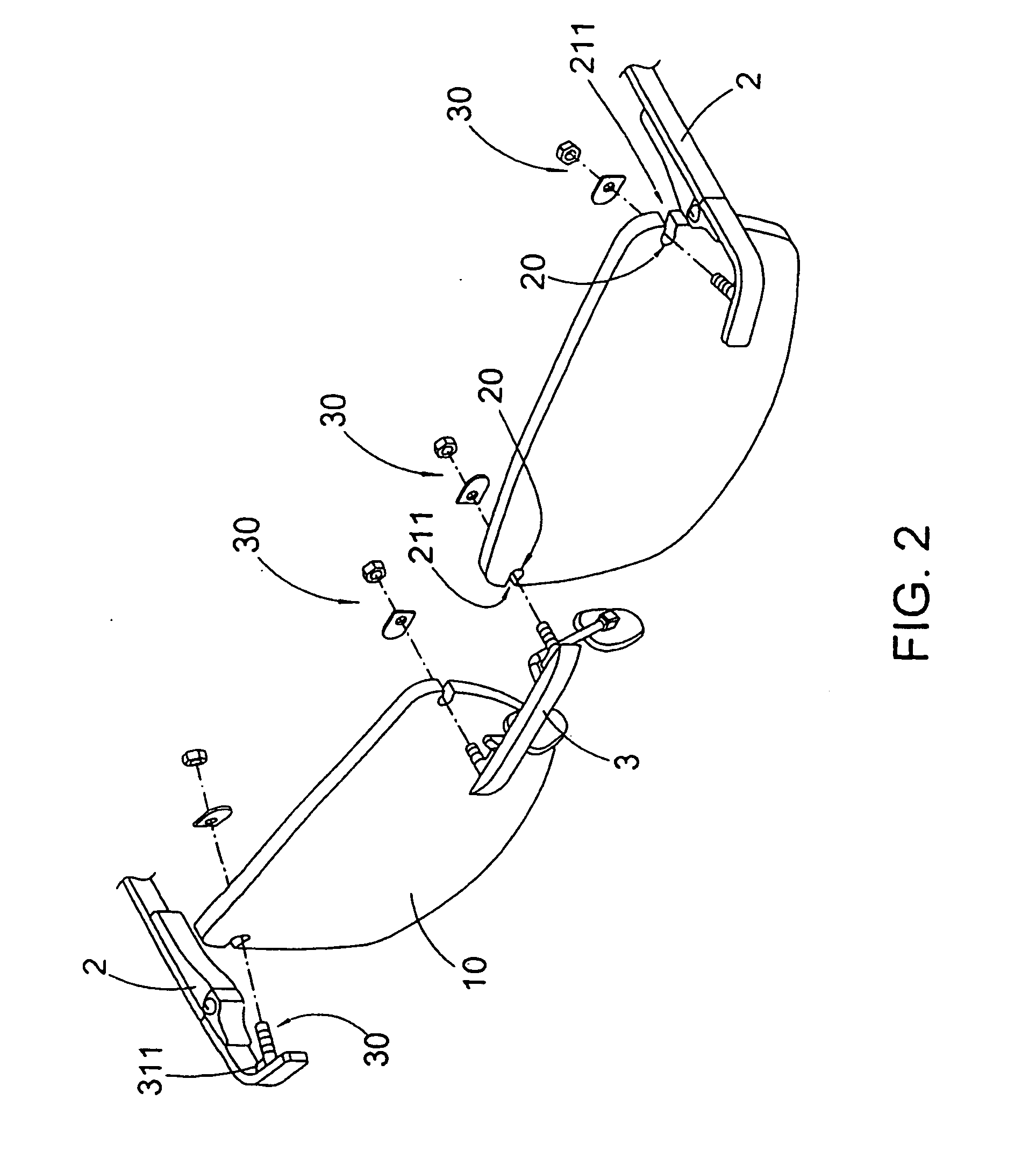
[0102]FIGS. 19 and 20 illustrate an alternative mode of the rimless spectacles of the fifth embodiment, wherein the second connectors 30D is adapted to incorporate with the first connector 20 as shown in FIG. 3. As shown in FIGS. 3, 19, and 20, each of the first connectors 20 is a coupling slot 20 indently formed at the peripheral edge 13 of the respective lens 10 to define the opening edges 21 and the coupling groove 25. As it is mentioned above, the distance between the two side surfaces 22 is larger than the distance between the two opening edges 21 such that the width of the opening 211 is smaller that the distance between the two side surfaces 22. Preferably the coupling groove 25 has a size slightly larger than the circumferential size of the elastic inserter 311D.

[0103]When the elastic inserter 311D is slidably passed through the respective coupling slot 20 at the front side of the lens 10, the enlarged head 3112D is located at the rear side of the lens 10. In particularly, t...

second embodiment

[0104]FIGS. 21 to 24 illustrate an alternative mode of the rimless spectacles of the As shown in FIGS. 21 to 24, each of the second connectors 30E comprises a connecting member 31E and a clipping member 32E, wherein the connecting members 31E are provided at the temple units 2 and the bridge 3 respectively. Each of the connecting members 31A comprises a retention inserter 311E and a coupling shaft 312E, wherein the retention inserter 311E has a shape and size corresponding to the shape and size of the respective coupling slot 25. Each of the retention inserters 311E has a retention surface 3111E and a biasing surface 3112E, wherein the retention surface 3111E is shaped and sized corresponding to the curved contacting surface 24. When the retention inserter 311E is slidably inserted into the corresponding coupling slot 20 inwardly from the peripheral edge 13 of the lens 10, the retention surface 3111E of the retention inserter 311E is biased against the curved contacting surface 24 ...

sixth embodiment

[0109]FIGS. 25 to 27 illustrate an alternative mode of the spectacles of the sixth embodiment, wherein the spectacles is the rim-type spectacle incorporating with the connection mechanism. As shown in FIG. 25, the spectacles comprise two lenses 10F. Each of the lenses 10F has a front side 11F, a back side 12F, and a peripheral edge 13F located between the laterals of front and the rear sides 11F, 12F.

[0110]The spectacles further comprise a frame which comprises two lens rims 4F encirclingly holding around the peripheral edges 13F of the lenses 10F respectively, two temple units 2F extended from two outer sides of the lens rims 4F respectively, and a bridge 3F extended between two inner sides of the lens rims 4F respectively.

[0111]As shown in FIGS. 25 to 27, each of the lens rims 4F has a side opening 41F provided at the outer side to form a C-shaped structure and upper and lower engaging members 42F, 43F extended from two ends of the lens rim 4F at the side opening 41F, wherein when...


PUM


Abstract

A pair of rimless spectacles includes two lenses, a frame including two temple units and a bridge, and a connection mechanism. The connection mechanism includes a plurality of first connectors spacedly provided at the lenses at a predetermined location and a plurality of second connectors provided at a predetermined location of each of the temple units and the bridge respectively, wherein the second connectors are coupled with the first connectors respectively to couple the temple units at two outer sides of the lenses respectively and to couple the bridge between two inner sides of the lenses respectively in a tool-less manner.

Description

CROSS REFERENCE OF RELATED APPLICATION[0001]This is a Divisional application that claims the benefit of priority under 35 U.S.C. §119 to a non-provisional application, application Ser. No. 12 / 807,951, filed on Sep. 16, 2010 which is a Continuation-In-Part application that claims the benefit of priority under 35 U.S.C. §119 to a non-provisional application, application Ser. No. 12 / 384,411, filed on Apr. 3, 2009, now U.S. Pat. No. 7,967,431 which is a non-provisional application of a provisional application having an application No. 61 / 194,096 and a filing date of Sep. 23, 2008.BACKGROUND OF THE PRESENT INVENTION[0002]1. Field of Invention[0003]The present invention relates to spectacles, and more particularly to a rimless spectacles, wherein a plurality of coupling slots are located at the lenses to engage with the temples and the bridge, so as to allow the lenses to be quickly fastened on the temples and the bridge to form an entire body structure of the rimless spectacles.[0004]2. ...

Claims


Application Information

Patent Timeline
Patent Type & Authority Applications(United States)
IPC IPC(8): G02C1/02
CPCG02C1/02G02C1/00G02C1/023G02C1/08
Inventor SIU, YUDAI, WENJIE
Owner SIU YU
Why Eureka
Try Eureka