Organic electrolyte capacitor

a capacitor and electrolyte technology, applied in the field of organic electrolyte capacitors, can solve the problems of deterioration of the negative electrode, deterioration of the electrode, and decrease in capacity, and achieve the effects of improving the conductivity of the electrode, low internal resistance, and high performan

Active Publication Date: 2008-06-10
SUBARU CORP
View PDF12 Cites 26 Cited by
  • Summary
  • Abstract
  • Description
  • Claims
  • Application Information

AI Technical Summary

Benefits of technology

[0006]In order to solve the above problems, a battery that uses a carbon material such as graphite and the like for the negative electrode and uses a lithium-contained metal oxide such as LiCoO2 and the like for the positive electrode has been proposed. The battery is called a rocking-chair battery, in which lithium ions are supplied to the negative electrode from the lithium-contained metal oxide of the positive electrode by charging after the assembly of the battery, and lithium in the negative electrode returns to the positive electrode by discharging. The battery does not use metal lithium ions in the negative electrode, and only lithium take part in charging and discharging. Therefore, the battery is called a lithium ion secondary batter, and distinguished from a lithium battery using metal lithium. The battery is characterized by high voltage and high capacity.
[0010]In the above invention, since the current collector has that the holes penetrating the front and rear surfaces thereof are provided, so that lithium ions can pass through between the front and rear surfaces of the electrodes without being blocked by the current collectors, lithium ions can be carried electrochemically not only to the negative electrodes arranged in the vicinity of the lithium metal but also to the negative electrodes arranged away from the lithium metal through the through-holes, even in the laminated cell structure of a storage device, in which many electrodes are laminated. In addition, since lithium ions can move freely between electrodes through the through-holes, the organic electrolyte battery can be charged and discharged smoothly.
[0011]In the above method, an electrode is formed on an electrode current collector by coating a mixture of a binder resin and electrode active material that can carry lithium ions reversibly. However, a current collector having holes that penetrate the front and rear surfaces, for example, such as an expanded metal, has lower tensile strength than a metal foil having with the same thickness but no holes, therefore a thick current collector is required in an actual coating with an electrode active material, and this it is difficult to improve the energy and power density by making the electrode thin. Also, when the current collector is coated with the electrode active material on condition that holes of current collector are open, the electrode material passes through the through-holes, thereby being difficult to uniformly coat for the current collectors. Furthermore, electrodes materials applied at the through-holes or edge portions (end portion) of the current collector are likely to drop out, and it is difficult to manufactured a uniform electrode, whereby a short circuit can be induced in the battery, and the reliability and durability of the storage device can deteriorate.
[0012]It is an object of the invention to provide an organic electrolyte capacitor, which can be produced industrially, has high energy density, and power density and shows low resistance toward the movement of lithium ions, by using electrodes that have high conductivity, high strength, and high uniformity.DISCLOSURE OF THE INVENTION
[0013]As a result of intensive examination to solve the above problems, the present inventors found out that it is possible to improve conductivity of electrodes and to obtain a high performance organic electrolyte capacitor having low internal resistance and high power density, in which lithium ion can move easily, by forming conductive layers with conductive materials on current collectors, which have through-holes, as an electrode current collector, and using the electrodes that are positive and negative electrode active material layers formed on the electrode current collectors having through-holes, preferably, after at least part of the through-holes of the electrode current collectors which have been blocked previously, and then completed the invention.

Problems solved by technology

However, the above secondary battery has a practical problem in that, if the battery is charged or discharged repeatedly, the positive or negative electrode deteriorates, and thus the capacity decreases.
Particularly, there is a safety problem in that the deterioration of the negative electrode is accompanied by generation of needle-like lithium crystals, so called dendrite.
The dendrite breaks through a separator as the battery is charged and discharged repeatedly, which causes short-circuit in the battery, and the battery may explode at the end, leading to severe safety problem.
Therefore the electric double-layer capacitor cannot be practically used as driving power supplies for electric vehicles demanding high energy density.
However, a current collector having holes that penetrate the front and rear surfaces, for example, such as an expanded metal, has lower tensile strength than a metal foil having with the same thickness but no holes, therefore a thick current collector is required in an actual coating with an electrode active material, and this it is difficult to improve the energy and power density by making the electrode thin.
Also, when the current collector is coated with the electrode active material on condition that holes of current collector are open, the electrode material passes through the through-holes, thereby being difficult to uniformly coat for the current collectors.
Furthermore, electrodes materials applied at the through-holes or edge portions (end portion) of the current collector are likely to drop out, and it is difficult to manufactured a uniform electrode, whereby a short circuit can be induced in the battery, and the reliability and durability of the storage device can deteriorate.

Method used


Image

  • Organic electrolyte capacitor
  • Organic electrolyte capacitor
  • Organic electrolyte capacitor

Examples


first embodiment

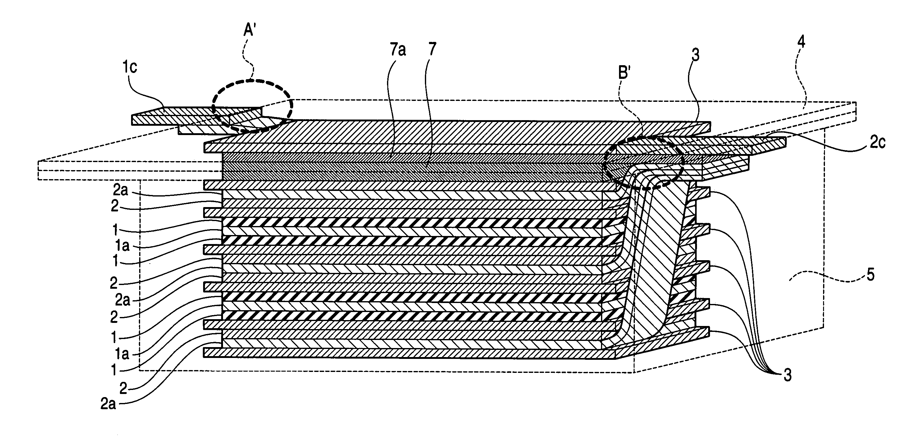
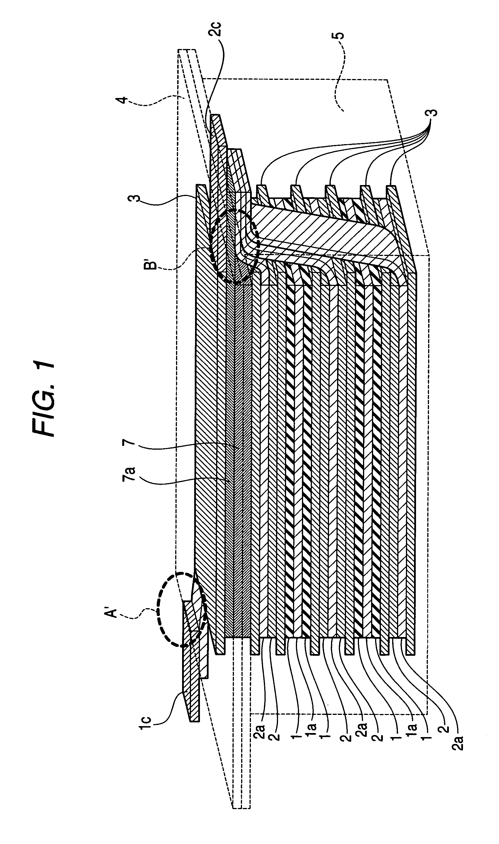
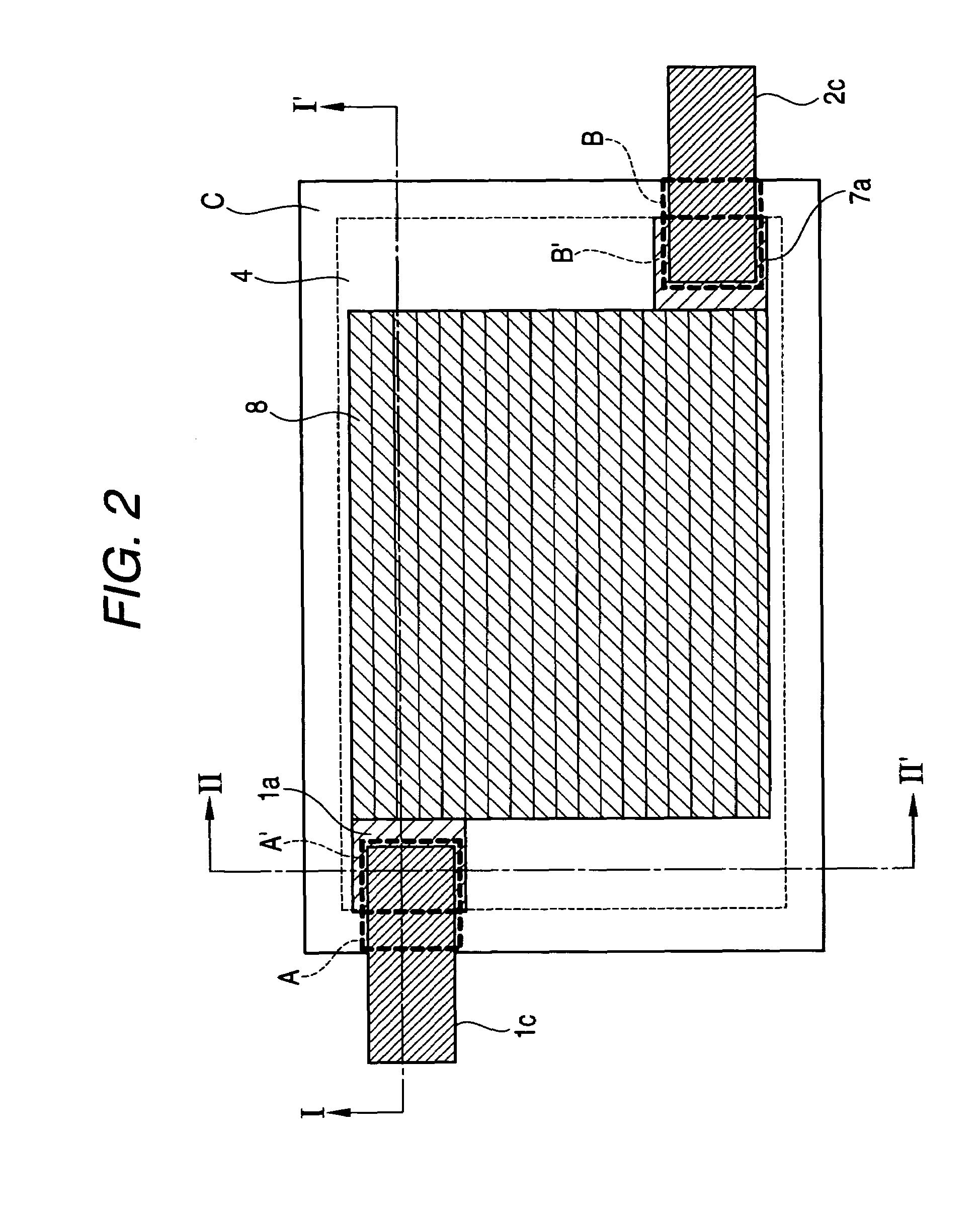
[0211]FIG. 1 is a perspective view of a film-type capacitor according to the first embodiment of the organic electrolyte capacitor of the invention. FIG. 2 is a plan view of the first embodiment, FIG. 3 is a cross-sectional view taken along the line I-I′ shown in FIG. 2, and FIG. 4 is a cross-sectional view taken along the line II-II′ shown in FIG. 2.

[0212]In the first embodiment, a three-electrode-laminated unit 8 is formed by providing a lithium electrode 7 on an electrode-laminated unit 6, in which electrode pairs including positive and negative electrodes are laminated sequentially.

[0213]In the first embodiment, the electrode-laminated unit 6 is formed using three negative electrode current collectors 2a and two positive electrode current collectors 1a. The positive and negative electrode current collectors 1a and 2a have holes penetrating the front and rear surfaces, and at least part of the through-holes are blocked with conductive materials 1b and 2b that are different from t...

second embodiment

[0224]Hereinafter, the second embodiment will be described. FIG. 13 is a plan view showing the second embodiment. FIG. 14 is a cross-sectional view taken along the line I-I′ shown in FIG. 13. Since the same numerals in the first and second embodiments denote the same components, only different portions will be described in detail.

[0225]As shown in FIG. 14, the sheet-shaped lithium electrodes 7 are disposed in the center of the roll-type structure in the second embodiment. The lithium electrodes 7 are formed on both surfaces of the lithium electrode current collector 7a. The positive electrode 1 is formed on a surface of a ribbon-shaped positive electrode current collector 1a, and the negative electrode 2 is formed on a surface of a ribbon-shaped negative electrode current collector 2a. Separator 3, negative electrode (2+2a), separator 3, and positive electrode (1+1a) are overlapped in this order and wound elliptically with the lithium electrode current collector 7a having the lithiu...

first example

Manufacturing Method of PAS Slurry for the Negative Electrode

[0238]PAS is synthesized by thermally treating a 0.5 mm-thick phenolic resin plate in a siliconit electric furnace, which increases the temperature up to 500° C. at a speed of 50° C. / hour, and then up to 650° C. at a speed of 10° C. / hour under nitrogen atmosphere. The PAS plate obtained in this way is grinded up by a ball mill so as to obtain PAS powder having an average particle size of 7 μm. The H / C ratio of the PAS powder is 0.22.

[0239]Next, 92 parts by weight of the above-mentioned PAS powder, 4 parts by weight of acetylene black powder, 4 parts by weight of SBR, 3.2 parts by weight of carboxymethylcellulose, and 120 parts by weight of ion-exchanged water are mixed sufficiently to obtain a slurry.

Measurement of the Capacitance Per Unit Weight of the Negative Electrode

[0240]The slurry is coated and dried on a surface of an 18 μm, thick copper foil, and then pressed so as to form a PAS negative electrode, the solid amoun...


PUM

PropertyMeasurementUnit
porosityaaaaaaaaaa
thicknessaaaaaaaaaa
total thicknessaaaaaaaaaa

Abstract

There is provided an organic electrolyte capacitor having electrodes on current collectors that have holes penetrating the front and rear surfaces, in which electrode materials formed on the through-holes of the current collectors seldom fall off and high energy density and high power density can be obtained. The organic electrolyte capacitor includes positive electrodes, negative electrodes and an electrolyte capable of transferring lithium ions, in which the positive electrodes contain a substance capable of carrying lithium ions and / or anions reversibly as a positive electrode active material, the negative electrodes contain a substance capable of carrying lithium ions as a negative electrode active material, the positive and negative electrodes possess the positive or negative electrode active material layers on an electrode substrate that has conductive layers made of conductive materials on current collectors, which have through-holes, and the negative electrodes carry lithium electrochemically.

Description

[0001]This is a U.S. National Phase Application under 35 U.S.C. §371 of International Patent Application No. PCT / JP2004 / 004469, filed Mar. 29, 2004, and claims benefit of Japanese Patent Application No. 2003 / 96664, filed Mar. 31, 2003 both of which are incorporated by reference herein. The International Application was published in Japanese on Nov. 11, 2004 as WO 2004 / 097867 A3 under PCT Article 21(2).CLEAN SPECIFICATIONDescription[0002]1. Technical Field[0003]The present invention relates to an organic electrolyte capacitor having high energy density and high output density and a current collector using the same, and particularly, to an organic electrolyte capacitor having high energy density and high output density, in which conductive layers are made of conductive materials on the current collectors having through holes that penetrate the front and rear surfaces, electrodes are formed with positive or negative electrode active material layers formed on the conductive layers, and ...

Claims


Application Information

Patent Timeline
Patent Type & Authority Patents(United States)
IPC IPC(8): H01G9/00B82Y99/00H01G11/22H01G9/02H01G9/04H01G11/30H01G11/50H01G11/56H01G11/66H01M4/13H01M4/133H01M4/137H01M4/587H01M4/60H01M4/66H01M4/70H01M4/74H01M10/052H01M10/0525H01M10/0566H01M10/0585H01M10/0587H01M10/36
CPCH01G9/016H01G9/058H01G9/155H01G11/06H01G11/12H01G11/28H01G11/60H01G11/62H01G11/70H01M4/133H01M4/137H01M4/602H01M4/667H01M4/70H01M4/742H01M10/052H01G11/32H01M10/0525H01M10/0585H01M10/0587Y02E60/122Y02E60/13Y02T10/7011Y02T10/7022Y02T10/70Y02E60/10Y02P70/50H01G11/30H01G11/54
Inventor ANDO, NOBUOKOJIMA, KENJITASAKI, SHINICHITAGUCHI, HIROMOTOFUJI, TSUTOMUHATO, YUKINORIMARUMO, CHISATO
Owner SUBARU CORP
Why Eureka
Try Eureka