Cutting insert and indexable cutting tool

a cutting tool and insert technology, applied in the field of cutting inserts and indexable cutting tools, can solve the problems of difficult to increase the feed rate to perform chipping and breakage, etc., to achieve more efficient high-feed cutting, prevent abnormal damage to the main cutting edge, and increase the feed rate

Active Publication Date: 2014-11-13
MITSUBISHI MATERIALS CORP
View PDF12 Cites 35 Cited by
  • Summary
  • Abstract
  • Description
  • Claims
  • Application Information

AI Technical Summary

Benefits of technology

[0063]As described above, according to the invention, in high-feed cutting, abnormal damage to the main cutting edge can be prevented by preventing a chip from having the largest thickness at the cutting boundary of the main cutting edge and preventing the thickness of a chip itself from becoming excessively large, and the feed rate can be further increased to perform more efficient high-feed cutting.

Problems solved by technology

Since the thickness of the chip becomes maximum on a cutting boundary of an outermost periphery of the main cutting edge, there is a concern that the main cutting edge of the cutting insert may cause abnormal damage, such as chipping and breakage, on the cutting boundary.
For this reason, the feed rate per one edge is suppressed to prevent the thickness of a chip from becoming excessively thick, and it is difficult to increase the feed rate to perform more efficient high-feed cutting.

Method used


Image

  • Cutting insert and indexable cutting tool
  • Cutting insert and indexable cutting tool
  • Cutting insert and indexable cutting tool

Examples


first embodiment

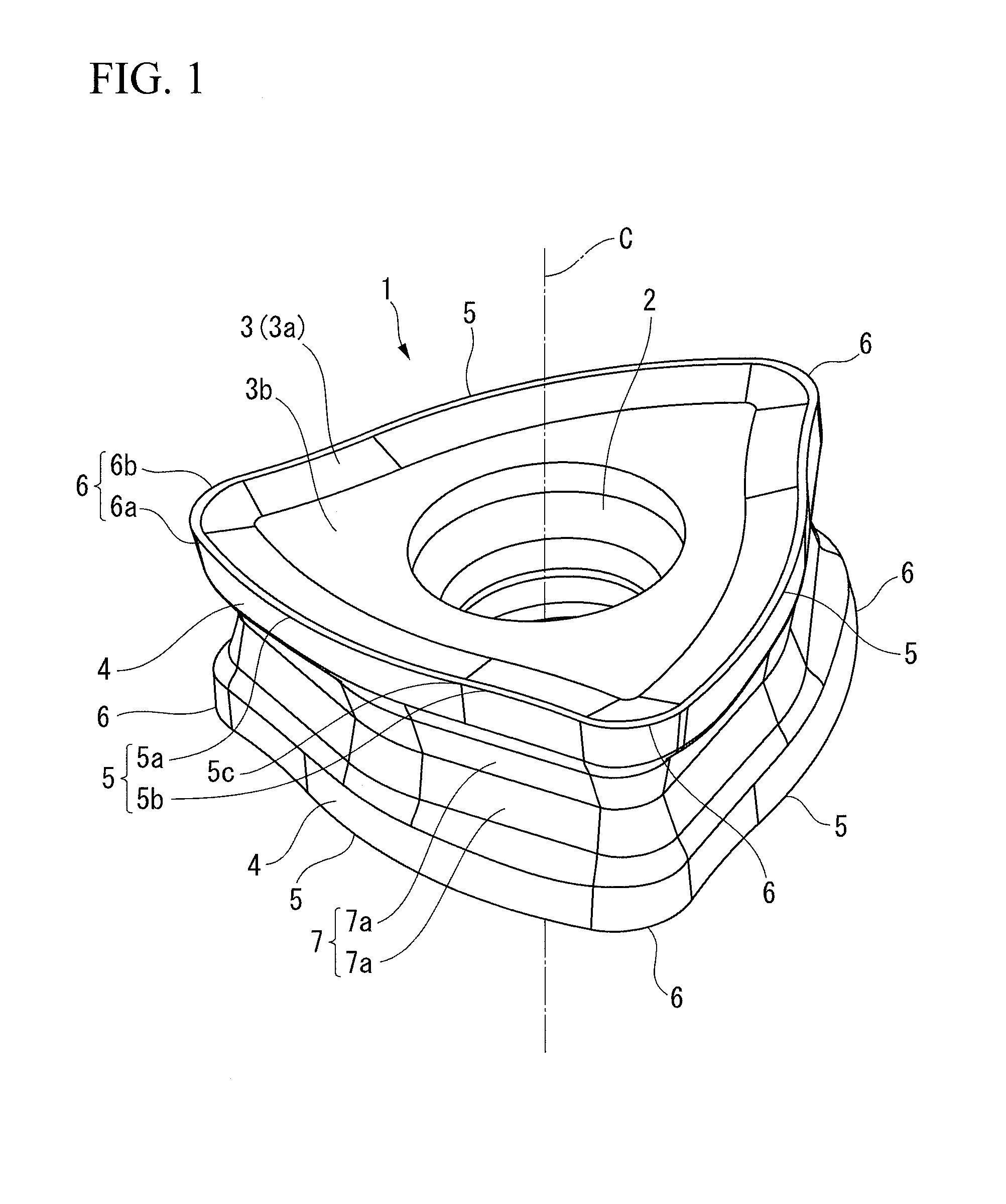
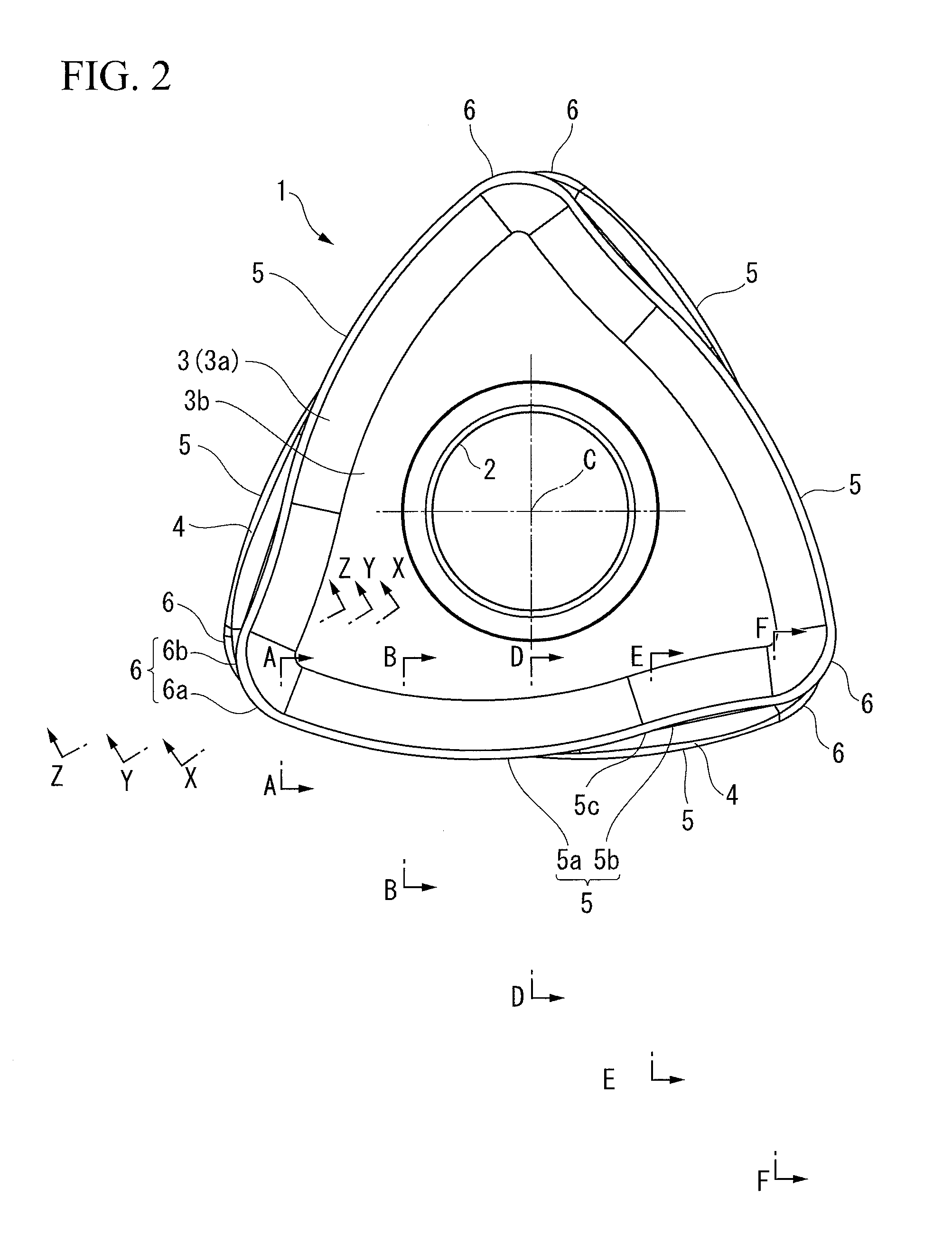
[0178]Meanwhile, in the cutting insert of the first embodiment, the insert body 1 has the equilateral triangular plate shape, the main cutting edges 5 are formed on the respective side ridges of the front and back polygonal surfaces having the equilateral triangular shape. However, the front and back polygonal surfaces are arranged so as to be slightly twisted around the insert centerline C passing through the center thereof, and the insert body 1 has the front-and-back inverted symmetrical shape with respect to the front and back polygonal surfaces.

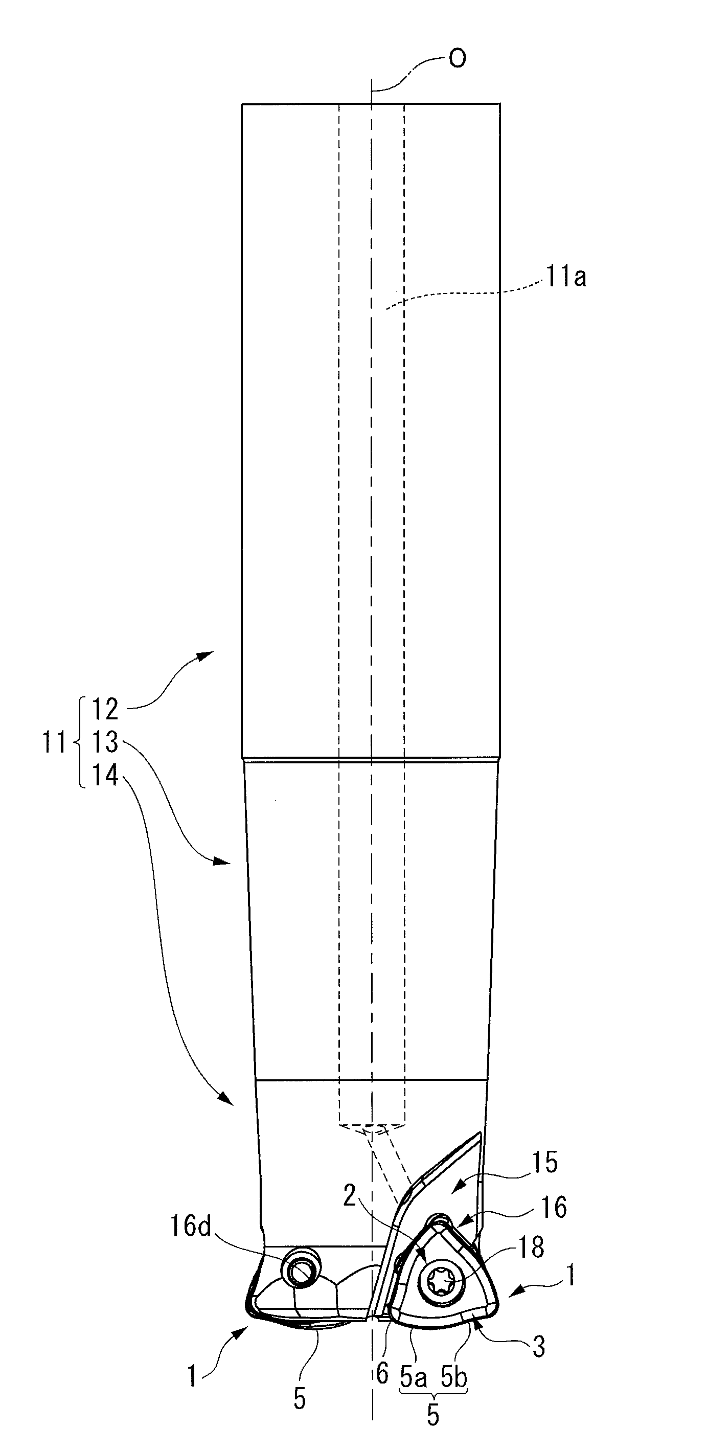
[0179]Such a cutting insert is attached to the insert mounting seat 16 of the end mill body 11 so that a side ridge is inclined so as to give a relatively small cutting edge angle to the main cutting edge 5 to be used for cutting and so that a negative axial rake angle and a negative radial rake angle are given to the main cutting edge 5. Accordingly, the rake face 3 of the other polygonal surface opposite to the one polygonal surface on...

second embodiment

[0190]Additionally, in the present embodiment, projections 3d are formed around the opening of the attachment hole 2 in the binding faces 3b of the front and back polygonal surfaces. The projections 3d have a substantially oblong shape when seen in the direction of the insert centerline C, and are formed on straight lines connecting the insert centerline C and the corner edges 6 in each binding face 3b. Three projections 3d are formed on equal intervals in the circumferential direction on one binding face 3b, and the projecting end surfaces, in the direction of the insert centerline C, of the three projections 3d in the one binding face 3b are located on one plane perpendicular to the insert centerline C. In accordance of the formation of such projections 3d, in the end mill body 11 of the indexable end mill of the second embodiment, as shown in FIG. 23, recesses 16f are formed on equal intervals in the circumferential direction around the screw hole 16d in the bottom surface 16a of...

third embodiment

[0198]Moreover, a honing is formed on the main cutting edge 5 and the corner edge 6 in the The honing in the present embodiment is a round honing 8, and as shown in FIGS. 27A to 27E, the intersecting ridgeline between the land 9 of the outer peripheral edge of the positive rake face 3a and the flank face 4 is formed in the shape of a convex curved surface, such as a convex circular arc in contact with the land 9 and the flank face 4 in a cross-section orthogonal to the intersecting ridgeline. This honing is formed over the whole circumference of the polygonal surface on which the rake face 3 is formed, and the position of a contact point between the land 9 and the round honing 8 serves as a projecting end of the main cutting edge 5 and the corner edge 6 in the thickness direction in the cross-section.

[0199]Among these, the size of the honing formed on the main cutting edge 5 is made larger toward the one end portion 5a at the other end portion 5b of the main cutting edge 5. That is...


PUM

PropertyMeasurementUnit
clearance angleaaaaaaaaaa
obtuse angleaaaaaaaaaa

Abstract

A cutting insert includes an insert body having a polygonal plate shape. Rake faces are formed on polygonal surfaces of the insert body, and flank faces are formed on lateral faces of the insert body arranged around the polygonal surfaces. Main cutting edges are formed on side ridges of the polygonal surfaces at intersecting ridgelines between the rake faces and the flank faces. Each main cutting edge extends between two corners adjacent to each other in a circumferential direction of the polygonal surface among corners of the polygonal surface. When seen from a direction opposing the rake face, one end portion of the main cutting edge that stretches to one corner of the two corners has a convexly curved shape, and the other end portion of the main cutting edge that stretches to the other corner of the two corners has a concavely curved shape.

Description

CROSS-REFERENCE TO RELATED PATENT APPLICATIONS[0001]This application is a U.S. National Phase Application under 35 U.S.C. §371 of International Patent Application No. PCT / JP2012 / 078171, filed Oct. 31, 2012, and claims the benefit of Japanese Patent Applications No. 2011-271369, filed on Dec. 12, 2011, No. 2012-022187, filed Feb. 3, 2012, and No. 2012-229181, filed Oct. 16, 2012, all of which are incorporated by reference in their entirety herein. The International Application was published in Japanese on Jun. 20, 2013 as International Publication No. WO / 2013 / 088851, under PCT Article 21(2).FIELD OF THE INVENTION[0002]The present invention relates to a cutting insert detachably attached to an indexable cutting tool to be used for milling, and an indexable cutting tool to which the cutting inserts are attached.BACKGROUND ART OF THE INVENTION[0003]As an indexable cutting tool, high-feed cutting of feeding an end mill body serving as a tool body at a high feed rate to cut a workpiece is...

Claims


Application Information

Patent Timeline
Patent Type & Authority Applications(United States)
IPC IPC(8): B23C5/20B23C5/10
CPCB23C5/207B23C5/205B23C5/109B23C2200/203B23C2210/50B23C2200/286B23C2200/08B23C5/2213B23C2200/0461B23C2200/0483B23C2200/125B23C2210/168B23C2200/081B23C2200/161Y10T407/192Y10T407/235B23C5/202
Inventor TAKAHASHI, HIDEBUMI
Owner MITSUBISHI MATERIALS CORP
Why Eureka
Try Eureka