Drive transmission group to a steer wheel of a vehicle

Inactive Publication Date: 2014-11-13
EUROSYST
View PDF4 Cites 3 Cited by
  • Summary
  • Abstract
  • Description
  • Claims
  • Application Information

AI Technical Summary

Benefits of technology

[0042]In this way the vehicle forks can be suspende

Problems solved by technology

These vehicles, though known, are rare as they are difficult to construct and exhibit considerable structural limitations, in particular in relation to the maximum steering radius possible with the drive transmis

Method used


Image

  • Drive transmission group to a steer wheel of a vehicle
  • Drive transmission group to a steer wheel of a vehicle
  • Drive transmission group to a steer wheel of a vehicle

Examples


Example

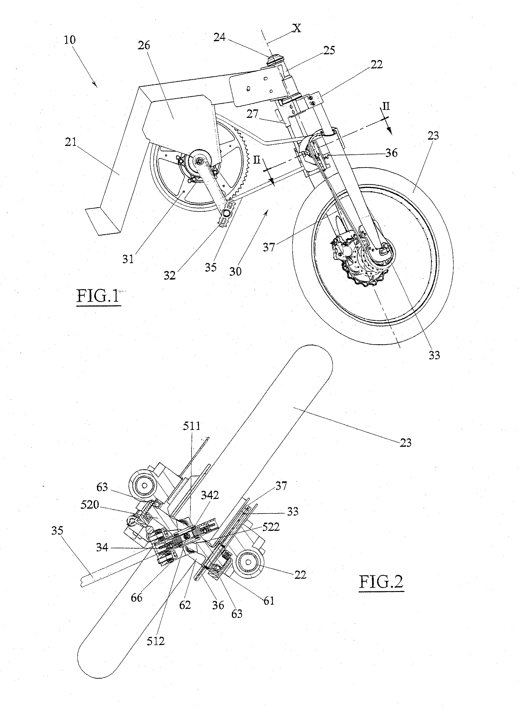
[0097]In a first embodiment, illustrated in FIGS. 1-10, the limiting means comprise a longitudinal appendage 64 (for example having a circular section) inserted in a sleeve 27 fixed to the frame 21, such that it can slide with respect to the frame, and provided with a cradle 65 which defines at least two lateral walls able to embrace the first intermediate chain ring 34 on opposite sides.

[0098]The cradle 65 is constrained in translation and hinged to the crossbar 62, by means of a hinge pine 660 coaxial (and / or parallel) to the steering axis X of the front wheel 23 (i.e. the fork 22 with respect to the frame 21).

[0099]In this way, the cradle 65 maintains the first intermediate chain ring 34 aligned with the frame 21 also during the steering of the front wheel 23.

[0100]The cradle 65 comprises revolving means, such as further bearings 66 (for example four in number, i.e. two per side) able to roll, substantially without dragging, on the lateral walls of the first intermediate chain ri...

Example

[0101]In a second embodiment shown in FIGS. 11-12, the limiting means comprise an articulated appendage 67 comprising a first portion 671, hinged to the frame 21 with respect to a first axis, that is substantially parallel to the rotation axis of the drive chain ring 31, and a second portion 672, hinged to the first portion 671 with respect to a second axis, parallel to the first axis.

[0102]A circular chain ring 673 is constrained to the free end of the second portion 672, which can be splined with play on the central shaft 520 and be rested on a flank of the first intermediate chain ring 34 (in particular of one of the annular bodies 343) in order to maintain it aligned with the frame 21 also during the steering of the front wheel 23.

[0103]Thus, apart from the function of the limitation of the rotation of the first intermediate chain ring 34, the sliding of the appendage 64 or the articulation of the articulated appendage 67 enable displacement of the fork 22 along the steering axi...


PUM


Abstract

A drive transmission group to a steer wheel of a vehicle at least a drive chain ring associable to actuating means in rotation able to impart a rotary motion to the chain ring, at least a driven chain ring solidly associated in rotation coaxially to the steer wheel, at least a first intermediate chain ring and a second intermediate chain ring connected respectively to the drive chain ring and to the driven chain ring by means of respective flexible organs, a universal joint comprising a joint spider on a first arm of which the first intermediate chain ring is associated, rotatably with respect to an axis of the first arm, and on a second arm of which the second intermediate chain ring is associated, rotatably with respect to an axis of the second arm, wherein the first intermediate chain ring is concentric to the spider.

Description

TECHNICAL FIELD[0001]The present invention relates to a drive transmission group to a steer wheel of a vehicle.[0002]In greater detail, the invention relates to a drive transmission group to a steer wheel of a three-wheeled vehicle, such as a tricycle (also “recumbent bike” or “trike”), an assisted-pedal bicycle, a motor cycle or the like.PRIOR ART[0003]Vehicles for transport of persons are known, such as recumbent bicycles or trikes, assisted-pedal bicycles or motorcycles, having three wheels, for example two rear wheels and a steering front wheel.[0004]These vehicle are classified in two main categories, of which a first category known as “rear wheel drive”, in which the drive wheels are the rear wheels, and a second category known as “front-wheel drive”, in which the drive wheel is the front wheel.[0005]In particular, the present invention relates to those vehicle in which the steer wheel is also the drive wheel, and in particular those front-wheel traction vehicles in which the ...

Claims


Application Information

Patent Timeline
IPC IPC(8): B62M1/36
CPCB62M1/36B62M23/00
Inventor BOVI, FABIO
Owner EUROSYST
Why Eureka
Try Eureka