Network Testing

a network and test technology, applied in the field of network testing, can solve the problems that the test cloud/distributed application faces major new challenges, and achieve the effect of reducing the complexity and effort of setting up the test, and lowering the cost of testing a network

Inactive Publication Date: 2014-11-13
NEC LAB AMERICA
View PDF10 Cites 83 Cited by
  • Summary
  • Abstract
  • Description
  • Claims
  • Application Information

AI Technical Summary

Benefits of technology

[0031]An objective of the present invention is to lower the cost of testing a network. The present invention also reduces complexity and effort of setting up a test environment.

Problems solved by technology

However, testing cloud / distributed applications faces major new challenges: Cloud applications are an intricate combination of complex and dynamically changing components such as virtual machines (VMs), servers and services that communicate through a potentially wide-area, unreliable and uncontrollable network connection such as the internet.
These faults are generally injected by forcing certain events (such as prematurely terminating instances of a running distributed service as in chaos monkey testing).
Many robustness issues of such distributed services are likely due to communication issues that are simply hard to test in the current standard test environments, which generally consist of a test server hosting many VMs.
However, this does not mean that the final deployed distributed application requires an OpenFlow-enabled network.

Method used


Image

  • Network Testing
  • Network Testing
  • Network Testing

Examples


example 1

[0070]Consider the simplified flow entry table presented in Table 1. It only shows rule matches based on the IP addresses of the sending host and the destination host. We assume that all other rule components are wildcard matches in this example. Each rule has a priority, which decides the order of processing. When a new packet arrives at a switch configured in this way, the rule with priority 17 will be analyzed first. If the packet originated at 192.168.10.10, the switch forwards it to port 3. However, if the packet originated from any other IP with prefix 192.168.10, then the packet is sent to port 7. If neither rule matches the incoming packet, and the packet originated at a host with IP prefix 192.168 and destination 192.168.10.5, the last rule is used to drop the packet. This could be for reasons of SPAM removal or firewall related issues. Finally, if none of the installed rules matches the incoming packet, the switch creates a PacketIn message to be sent to the controller for...

example 2

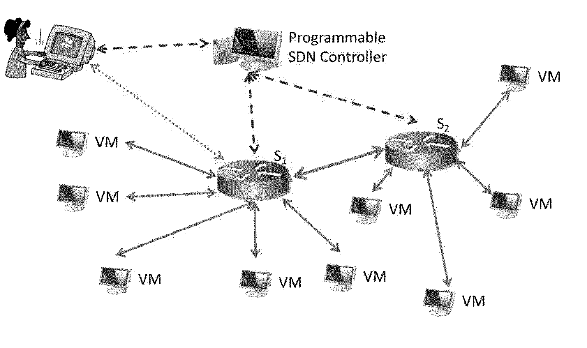
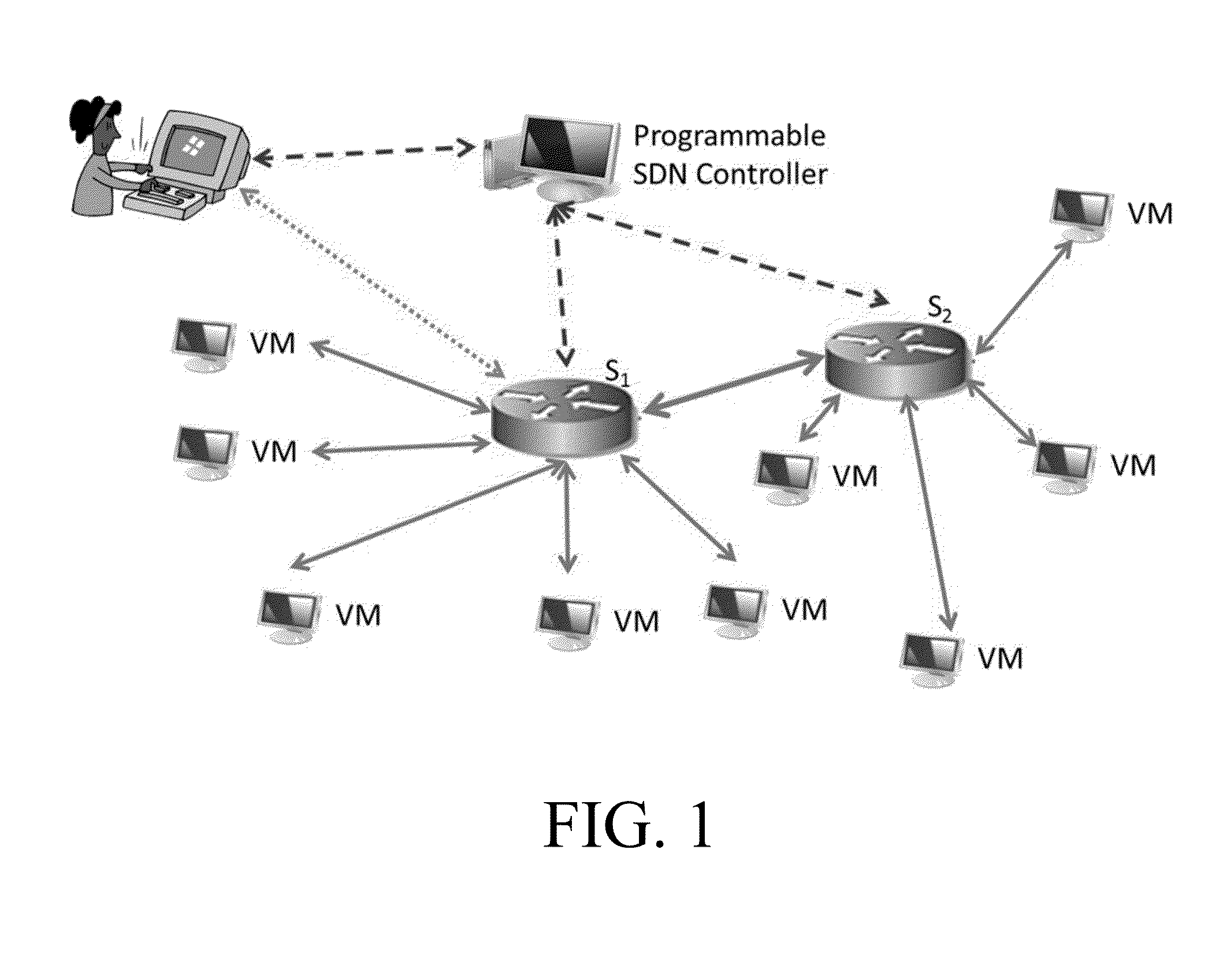
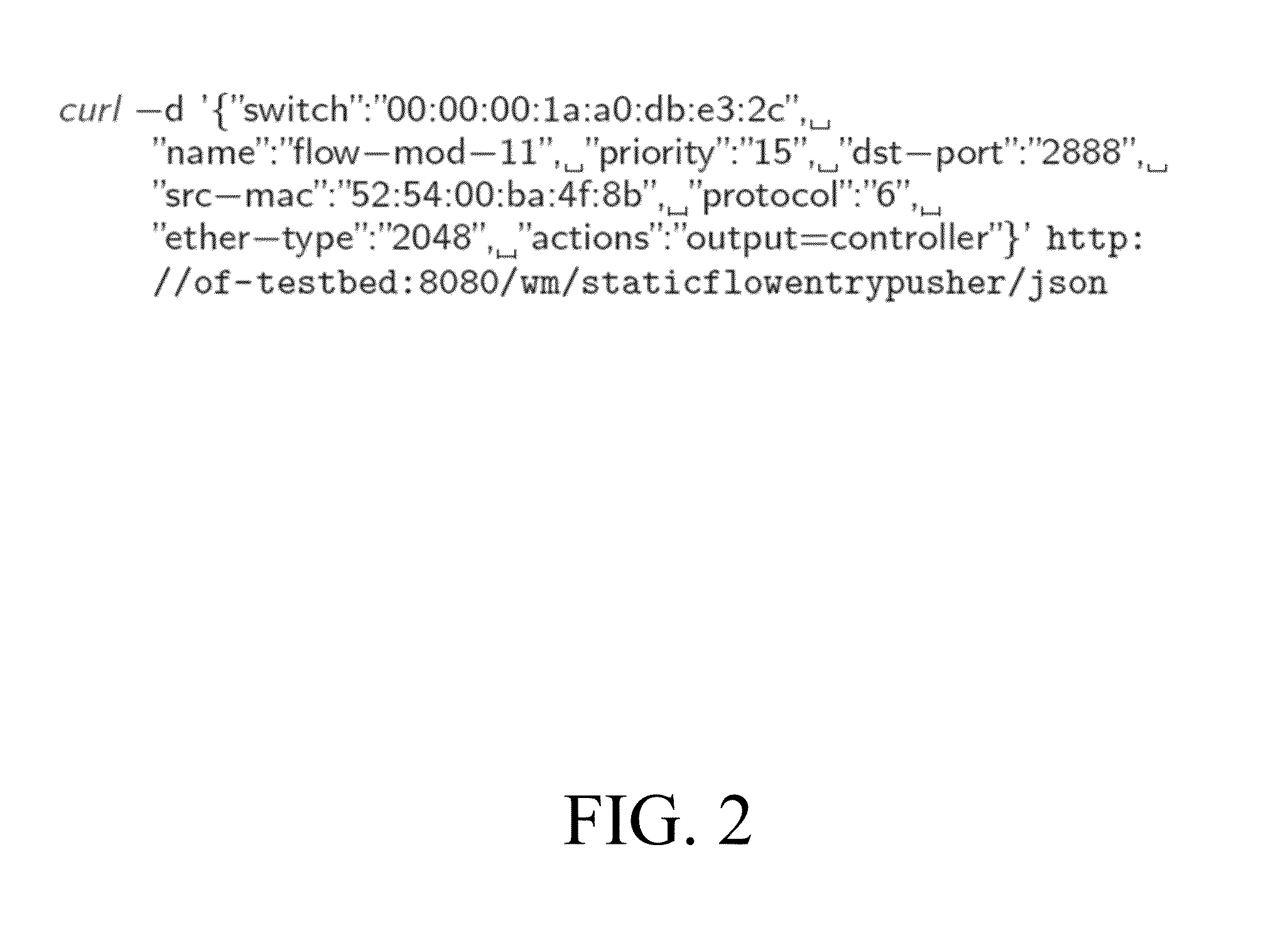
[0097]Consider the case where the tester analyzes the distributed service ZooKeeper (see http: / / zookeeper.apache.org). FIG. 1 shows a sample curl command that the tester can issue to the static flow entry pusher module. Here we model the effect of a bad connection from a particular source VM. As shown, the rule only matches on TCP packets (protocol 6), and one source VM. It applies only to messages that are sent to port 2888, the default port number that ZooKeeper uses for followers to connect to the leader. Thus, any other traffic originating from the sender VM would not be impacted by this rule. However, note that the rule does not specify a destination host. The tester can further specialize this rule by adding a destination MAC address to impact only traffic between two particular end host VMs.

[0098]This rule forwards all matching packets to the OpenFlow controller. The programmable controller, and thus the tester, can decide how to further process these packets. In our current ...


PUM


Abstract

A network testing method implemented in a software-defined network (SDN) is disclosed. The network testing method comprising providing a test scenario including one or more network events, injecting said one or more network events to the SDN using an SDN controller, and gathering network traffic statistics. A network testing apparatus used in a software-defined network (SDN) also is disclosed. The network testing apparatus comprising a testing system to provide a test scenario including one or more network events, to inject said one or more network events to the SDN using an SDN controller, and to gather network traffic statistics. Other methods, apparatuses, and systems also are disclosed.

Description

[0001]This application claims the benefit of U.S. Provisional Application No. 61 / 821,796, entitled “SDTN: Software-Defined Testing Network,” filed on May 10, 2013, the contents of which are incorporated herein by reference.BACKGROUND OF THE INVENTION[0002]The present invention relates to network testing and, more particularly, to network testing of a software-defined network (SDN).[0003]The recent emergence of cloud computing—the use of hardware or software computing resources over a network such as the internet—has led to new opportunities for large-scale systems such as Big Data applications. End users of cloud-based applications often entrust the user's data to remote services by software and infrastructure providers. For example, in the Software as a Service (SaaS) business model, the end user typically accesses the on-demand provided software through a thin client via a web browser, while the user's data is stored at the application-service provider. According to a recent estim...

Claims


Application Information

Patent Timeline
Patent Type & Authority Applications(United States)
IPC IPC(8): H04L12/26
CPCH04L43/50H04L41/04H04L41/5096H04L41/40H04L41/344H04L41/342H04L43/20
Inventor IVANCIC, FRANJOLUMEZANU, CRISTIANBALAKRISHNAN, GOGULDENNIS, WILLARDGUPTA, AARTI
Owner NEC LAB AMERICA
Why Eureka
Try Eureka