User interface devices

Active Publication Date: 2014-11-20
SEESCAN
View PDF5 Cites 38 Cited by
  • Summary
  • Abstract
  • Description
  • Claims
  • Application Information

AI Technical Summary

Benefits of technology

[0010]In another aspect, a user interface device may include spring arrays which may be configured with radially oriented springs that may secure and allow displacements of the actuator element relative to the fixed base and top assembly of the frame. Multiple concentric assemblies of radially

Problems solved by technology

However, such interface devices fail to efficiently handle scenarios where more than two degrees of freedom need to be sensed and/or controlled.
Some existing user interface d

Method used


Image

  • User interface devices
  • User interface devices
  • User interface devices

Examples


embodiment 100

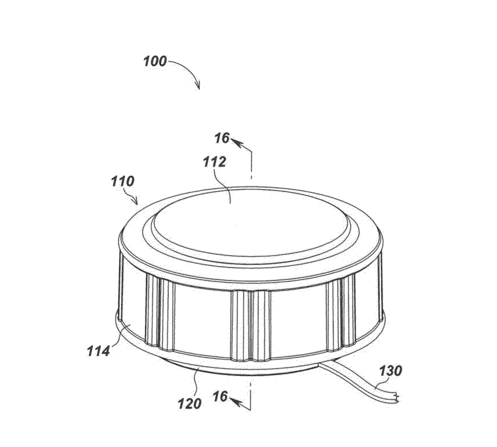
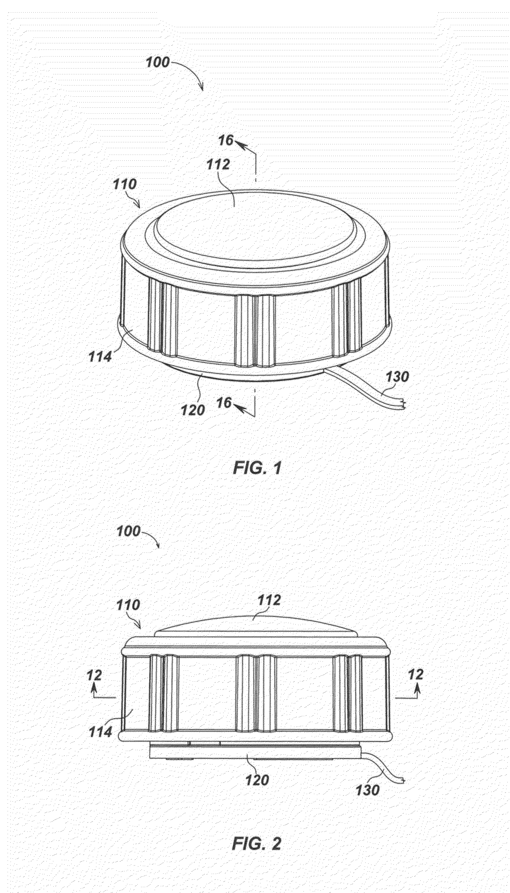
[0134]The top assembly 110 may include a top outer plate 112 and an actuator grip cover or boot 114, which may be separate elements or may be integrally formed in some embodiments. The actuator grip cover may be formed to conform to and cover the actuator assembly, such as by being close to or in contact with an outer actuator element or grip element. The actuator grip cover 114 may include a raised or textured surface or surface elements of various types. For example, FIG. 1 illustrates a series of vertically-oriented raised bars, while FIG. 35 illustrates an alternate embodiment with a “diamond plate” surface with raised diamond-shaped features. Various other surface features, such as raised or indented circles, ovals, lines, grids, etc. may be used in alternate embodiments. If separately formed, the grip cover or boot 114 may cover all or part of the top as well as all or part of the sides of the UID (in effect covering the actuator assembly which in internal to the cover 114 as ...

embodiment 430

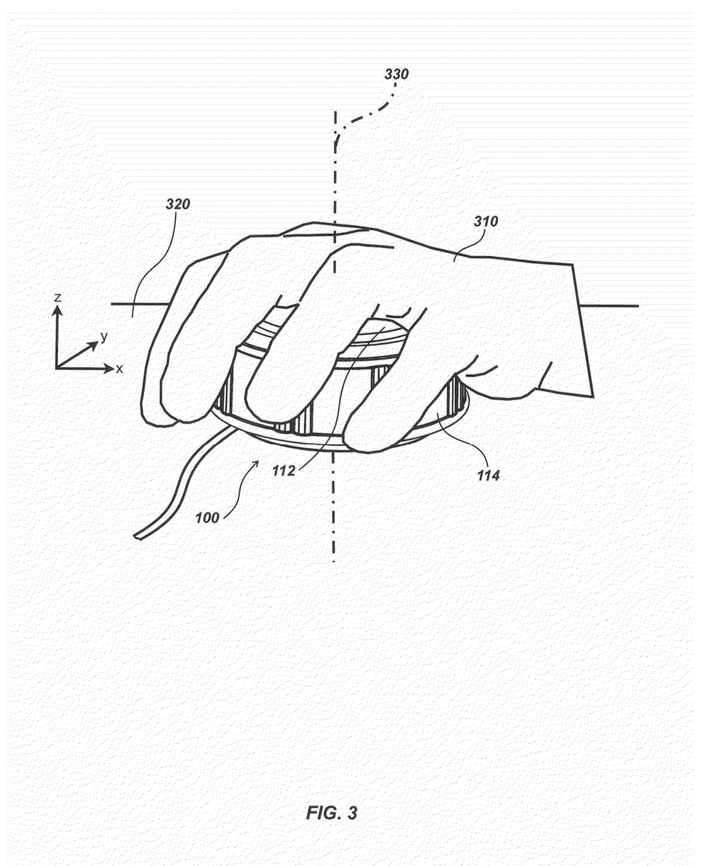
[0135]As noted previously, in an exemplary embodiment, the top assembly is fixed in position relative to the bottom or base assembly, with the movable actuator assembly in between (the actuator assembly is covered in FIG. 1 by the grip cover 114, but is shown in part in embodiment 430 in FIG. 4). By fixing the top of the UID relative to the base, a user may grip either the base or top (or both) with one hand and simultaneously move, twist, rotate, squeeze, lift up or down, etc. the actuator assembly relative to the base and top. By fixing the top relative to the base (where the base is typically disposed on a surface such as a desk, etc., or on or within another device such as a tablet, notebook computer, phone, etc.), one or more switches or buttons may be disposed below the top surface (e.g., under grip cover 114) and may be actuated by the user by pressing on a corresponding area of the top while holding the edge of the top and / or the base. In one embodiment corresponding to a co...

embodiment 1900

[0173]The actuator cover 1940 may comprise a pliant material such as elastomer or similar material and be made to move and flex during displacements of the actuator components, similarly to the actuator cover illustrated in FIGS. 1-10. The actuator cover 1940 may further be formed or shaped to circumscribe actuator components within the user interface device 1900 and aid in preventing unwanted external substances, such as dust or fluids, from accessing the internal workings of the user interface device embodiment 1900.

[0174]The various actuator components, as well as the actuator cover 1940, may be configured to allow movement relative to the top plate 1912 and base assembly 1920 which are fixed relative to each other. In this way, the top plate 1912 may allow a user's hand to rest while still displacing the actuator element and pressing or clicking of the button features 1914. In addition, the force from a user's hand resting upon the user interface device 1900 may aid in holding t...


PUM


Abstract

User interface devices (UIDs) for sensing position or motion of an actuator assembly in multiple degrees of freedom are disclosed. In one embodiment a UID includes a frame having a top and bottom assembly, an actuator assembly disposed within a volume between the top and bottom of the frame having magnets disposed therein, a sensor array for sensing magnetic fields from the magnets in multiple axes, and a processing element for receiving the sensed magnet fields and generating a UID output signal corresponding to a position, translation, rotation, deformation, or other action of the actuator assembly.

Description

CROSS-REFERENCE TO RELATED APPLICATIONS[0001]This application claims priority under 35 U.S.C. §119(e) to co-pending U.S. Provisional Patent Application Ser. No. 61 / 824,965, entitled DUAL SPRING MAGNETICALLY SENSED USER INTERFACE DEVICES, Filed May 17, 2013, the content of which is incorporated by reference herein in its entirety for all purposes.FIELD[0002]This disclosure relates generally to user interface devices for use with computers, gaming systems, control systems, and other electronic computing devices and systems or associated equipment. More specifically, but not exclusively, the disclosure relates to magnetically sensed user interface apparatus, devices, and systems using magnets and multi-axis magnetic sensors to determine user-applied actuator positions, displacements and / or deformations in multiple dimensions and degrees of freedom.BACKGROUND[0003]The use of devices to interface with computers, gaming systems, control systems, and other electronic devices and systems ha...

Claims


Application Information

Patent Timeline
IPC IPC(8): G06F3/02G06F3/01
CPCG06F3/016G06F3/0202G06F3/0338
Inventor OLSSON, MARK S.COX, DAVID A.
Owner SEESCAN
Why Eureka
Try Eureka