Liquid crystal display device, method of controlling liquid crystal display device, control program of liquid crystal display device, and storage medium for the control program

a liquid crystal display device and control program technology, applied in the direction of electric digital data processing, instruments, computing, etc., can solve the problems of difficult to discharge an electric charge accumulated in a pixel, image sticking, image sticking, etc., to reduce the capacity of electric power supply, shorten the time required for applying, and reduce the effect of electric power required

Inactive Publication Date: 2014-11-20
SHARP KK
View PDF6 Cites 8 Cited by
  • Summary
  • Abstract
  • Description
  • Claims
  • Application Information

AI Technical Summary

Benefits of technology

[0012]With the configuration, in a case where a given voltage for power-off processing is applied while the power supply is being turned off, it is possible to prevent a voltage from continuing to be applied to a pixel during a period in which the power supply is turned off. In a case where a switching cycle of a gate bus line, via which writing is carried out, is set shorter during power-off processing than during image display, it is possible to shorten a time required for applying the given voltage to each picture element. This allows a reduction in electric power required for power-off processing. Therefore, it is possible to reduce a capacity of electric power supply means which supplies drive electric power for power-off processing, thereby allowing a reduction in cost.

Problems solved by technology

It has been conventionally known that, in a case where electric fields of identical polarities are continuously applied to pixels of a liquid crystal display device, polarization of liquid crystal molecules occurs, thereby causing a problem such as image sticking and a change in characteristic of a pixel.
It has also been known that a phenomenon of image sticking occurs in a case where a power supply to a liquid crystal display device is turned off while displaying an image.
Note, however, that, since this type of liquid crystal display device has a small off-leak electric current, it is difficult to discharge an electric charge which has been accumulated in a pixel, while a power supply to the liquid crystal display device is being turned off.
This easily causes the above problems.

Method used


Image

  • Liquid crystal display device, method of controlling liquid crystal display device, control program of liquid crystal display device, and storage medium for the control program
  • Liquid crystal display device, method of controlling liquid crystal display device, control program of liquid crystal display device, and storage medium for the control program
  • Liquid crystal display device, method of controlling liquid crystal display device, control program of liquid crystal display device, and storage medium for the control program

Examples


embodiment 1

[0032]The following description will discuss Embodiment 1 of the present invention.

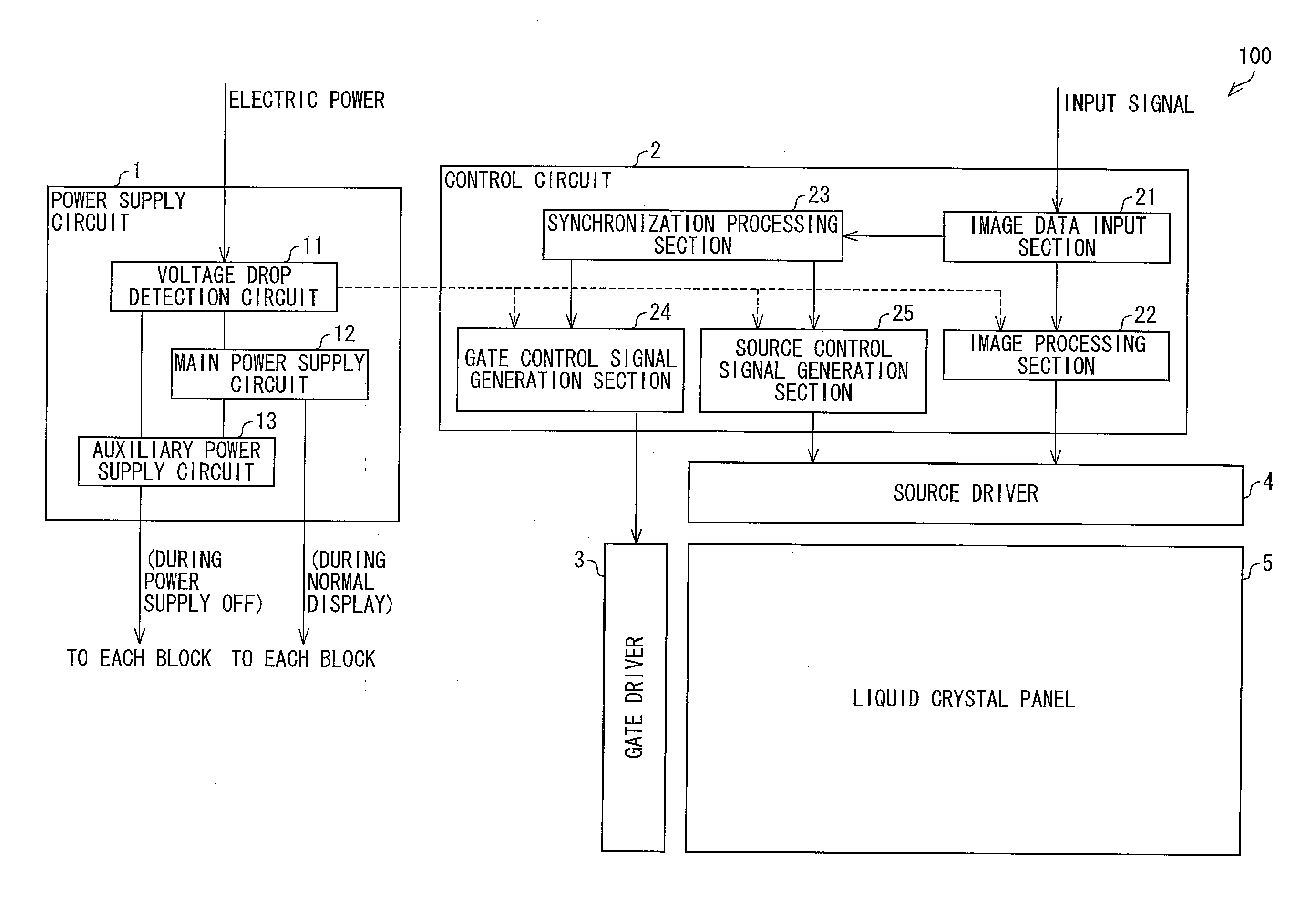
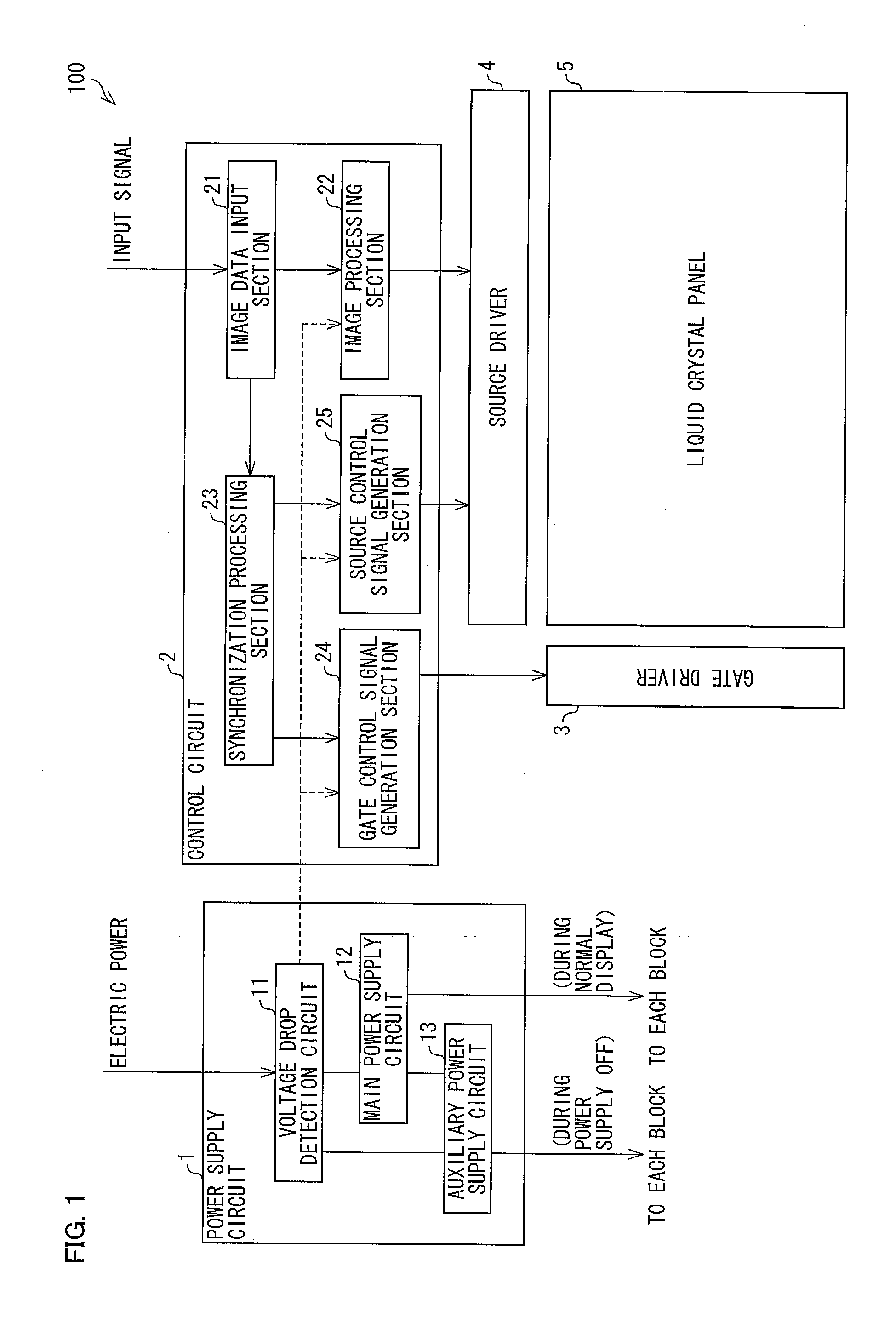
[0033]FIG. 1 is an explanatory diagram illustrating a schematic configuration of a liquid crystal display device 100 of Embodiment 1. The liquid crystal display device 100 includes a power supply circuit 1, a control circuit (control means) 2, a gate driver 3, a source driver 4, and a liquid crystal panel 5 (see FIG. 1).

[0034]The power supply circuit 1 (i) receives electric power externally supplied (e.g., supplied from a commercial power supply, a private generation power supply, or a charging device) and (ii) supplies electric power to each block (each section) of the liquid crystal display device 100. The power supply circuit 1 includes a voltage drop detection circuit 11, a main power supply circuit 12, and an auxiliary power supply circuit 13.

[0035]The voltage drop detection circuit (voltage detection means) 11 monitors an input voltage externally supplied and detects that a power supply to the l...

embodiment 2

[0103]The following description will discuss Embodiment 2 of the present invention. For convenience, members which have functions identical with those illustrated in the drawings of Embodiment 1 are given identical reference numerals, and are not described repeatedly.

[0104]FIG. 15 is an explanatory diagram illustrating an example of a control signal of the liquid crystal panel 5 of the liquid crystal display device 100 of Embodiment 2. (a) of FIG. 15 illustrates a control signal which is used during normal display. (b) of FIG. 15 illustrates a control signal which is used during power-off processing.

[0105]As illustrated in (a) of FIG. 15, during normal display, an electric potential of a gate bus line 31 to be selected is switched to high level in synchronization with a timing when a gate clock signal GCK switches from low level to high level after a gate start pulse GSP becomes high level. A gate enable signal GOE switches from low level to high level, during a given period immedia...

embodiment 3

[0112]The following description will discuss Embodiment 3 of the present invention. For convenience, members which have functions identical with those illustrated in the drawings of Embodiments 1 and 2 are given identical reference numerals, and are not described repeatedly.

[0113]FIG. 16 is an explanatory diagram illustrating an example of a control signal of the liquid crystal panel 5 of the liquid crystal display device 100 of Embodiment 3. (a) of FIG. 16 illustrates a control signal which is used during normal display. (b) of FIG. 16 illustrates a control signal which is used during power-off processing.

[0114]As illustrated in (a) of FIG. 16, an operation carried out during normal display is identical to that described in Embodiment 1 (see (a) of FIG. 14).

[0115]As illustrated in (b) of FIG. 16, a cycle of a gate clock signal GCK is set shorter during power-off processing than during normal display. A gate start pulse GSP is switched to high level a plurality of times (twice in th...


PUM


Abstract

While a power supply to a liquid crystal display device (100) is being turned off, a control circuit (2) sets a switching cycle of a gate bus line, via which writing is carried out, shorter than that during image display and carries out power-off processing in which a given voltage for power-off processing is applied to each source bus line. This makes it possible to provide, without greatly increasing a device cost, a liquid crystal display device capable of preventing a voltage from continuing to be applied to a pixel while the power supply is being turned off.

Description

[0001]This Nonprovisional application claims priority under 35 U.S.C. §119 on Patent Application No. 2013-105504 filed in Japan on May 17, 2013, the entire contents of which are hereby incorporated by reference.TECHNICAL FIELD[0002]The present invention relates to a technique for preventing a voltage from continuing to be applied to a pixel of a liquid crystal display device while a power supply to the liquid crystal display is being turned off.BACKGROUND ART[0003]It has been conventionally known that, in a case where electric fields of identical polarities are continuously applied to pixels of a liquid crystal display device, polarization of liquid crystal molecules occurs, thereby causing a problem such as image sticking and a change in characteristic of a pixel. It has also been known that a phenomenon of image sticking occurs in a case where a power supply to a liquid crystal display device is turned off while displaying an image. This is because a voltage, applied to each of pi...

Claims


Application Information

Patent Timeline
Patent Type & Authority Applications(United States)
IPC IPC(8): G09G3/36
CPCG09G3/3696G09G3/3614G09G3/3677G09G2310/067G09G2320/0204G09G2320/0257G09G2330/027
Inventor SAWABE, DAIICHINISHIDO, MASANORI
Owner SHARP KK
Why Eureka
Try Eureka