Universal sphygmomanometer simulator for live training and evaluation

a simulator and sphygmomanometer technology, applied in the field of universal sphygmomanometer simulator for live training and evaluation, can solve the problems of not being able to use in environments too noisy to permit hearing the characteristic sounds, and possibly less accurate, and unable to achieve calibration

Active Publication Date: 2014-11-20
PORT
View PDF3 Cites 7 Cited by
  • Summary
  • Abstract
  • Description
  • Claims
  • Application Information

AI Technical Summary

Benefits of technology

[0027]One aspect of the present invention provides a universal sphygmomanometer simulator for live training and evaluation. The term “universal” within the meaning of this application is intended to indicate that the simulator of the present invention can be used with any manikin brand for manikin based simulated patients and also with live simulated patients. The concept that the simulator is for “live training” indicates, within the meani

Problems solved by technology

They are used by trained practitioners, and cannot be used in environments too noisy to permit hearing the characteristic sounds.
Aneroid sphygmomanometers are considered safer than mercury based, although possibly less accurate.
A major cause of departure from calibration is mechanical jarring.
In addition to the digital oscillometric monitors drawbacks where they cannot be used, the overall accuracy of such devices has been questioned.
Too small a cuff 16 results in too high a pressure, while too large a cuff 16 results in too low a pressure.
The electronically generated sounds are digitally recorded.” While these simulators provide effective tools for supplying the trainees with a wide range of blood pressures to obtain and provide a method of verifying the accuracy of the trainee's results, they do not provide the real live aspects of interacting with a human regardless of how “lifelike” the syste

Method used


Image

  • Universal sphygmomanometer simulator for live training and evaluation
  • Universal sphygmomanometer simulator for live training and evaluation
  • Universal sphygmomanometer simulator for live training and evaluation

Examples


Embodiment Construction

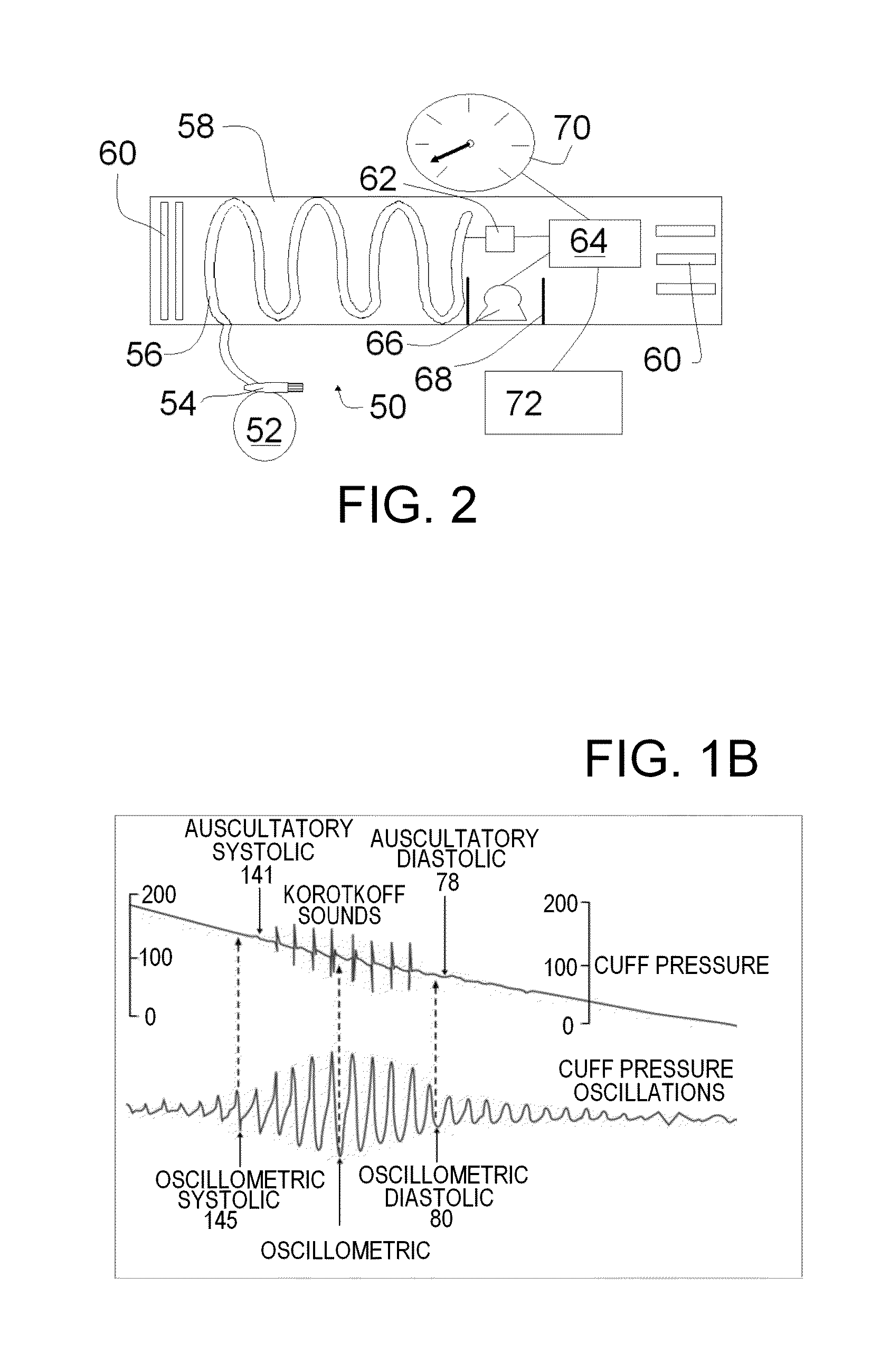
[0038]FIGS. 2, 3 and 4A are schematic illustrations of a universal sphygmomanometer simulator 50 for live training and evaluation formed according to one aspect of the present invention. FIG. 3 is an exploded view of the sphygmomanometer simulator 50 showing the exterior of the cuff 58 above the inner cuff 58. While most aspects of the invention are clear in both figures, some aspects are better illustrated in FIG. 2 while others are better illustrated in the FIG. 3. FIG. 4A is another schematic illustration of a universal sphygmomanometer simulator 50 for live training and evaluation formed according to one aspect of the present invention which can be better described after the embodiments of FIGS. 2 and 3. FIG. 4B is a schematic illustration of the universal sphygmomanometer simulator 50 for live training and evaluation of FIG. 4A with the cuff removed for clarity.

[0039]As discussed above and further elaborated herein the term universal is intended to indicate that the simulator 5...


PUM


Abstract

A sphygmomanometer simulator for live training includes an upper arm cuff for a simulated patient; a rigid walled pressure vessel within the cuff; a manual inflator and manual release valve coupled to the rigid walled vessel to selectively increase and release the pressure within the pressure vessel; a pressure sensor coupled to the pressure vessel; a cuff controller receiving the pressure sensor measurements and controlling a speaker within the cuff to emit designated simulated Korotkoff sounds associated with a simulated blood pressure and with the pressure of the pressure vessel; a visual gauge controlled by the cuff controller and displaying a pressure associated with the pressure in the pressure vessel and simulated Korotkoff gauge bumps associated with the simulated blood pressure for the simulated patient; and a user controller coupled to the cuff controller for inputting the simulated blood pressure for the simulated patient.

Description

RELATED APPLICATIONS[0001]This application claims the benefit of U.S. Provisional Patent Application Ser. No. 61 / 824,939, filed May 17, 2013 entitled “Universal Sphygmomanometer Simulator For Live Training And Evaluation” which is incorporated herein by reference.BACKGROUND INFORMATION[0002]1. Field of the Invention[0003]The present invention relates to a universal sphygmomanometer simulator for live training and evaluation.[0004]2. Background Information[0005]Sphygmomanometer[0006]Blood pressure refers to the force exerted by circulating blood on the walls of blood vessels, and constitutes one of the principal vital signs of a patient or subject (human or animal). The pressure of the circulating blood decreases as blood moves through arteries, arterioles, capillaries and veins; the term blood pressure generally refers to arterial blood pressure, i.e., the pressure in the larger arteries, arteries being the blood vessels which take blood away from the heart. Blood pressure in humans...

Claims


Application Information

Patent Timeline
IPC IPC(8): G09B23/28A61B5/022
CPCA61B5/022G09B23/28G09B23/288
Inventor OLMSTEAD, CLIFFORD D.MILLER, CHARLES G.WOODS, JERRYDHINGRA, SUKHTEJ
Owner PORT
Why Eureka
Try Eureka