
Hair cutting device

a cutting device and hair technology, applied in the field of hair cutting devices, can solve the problems of reducing the height of the skin dome, the size of the slit, and the construction of the device is more complex, so as to achieve the effect of reducing irritation and improving closeness

Inactive Publication Date: 2014-11-27
KONINKLIJKE PHILIPS ELECTRONICS NV
View PDF0 Cites 11 Cited by
  • Summary
  • Abstract
  • Description
  • Claims
  • Application Information

AI Technical Summary

Benefits of technology

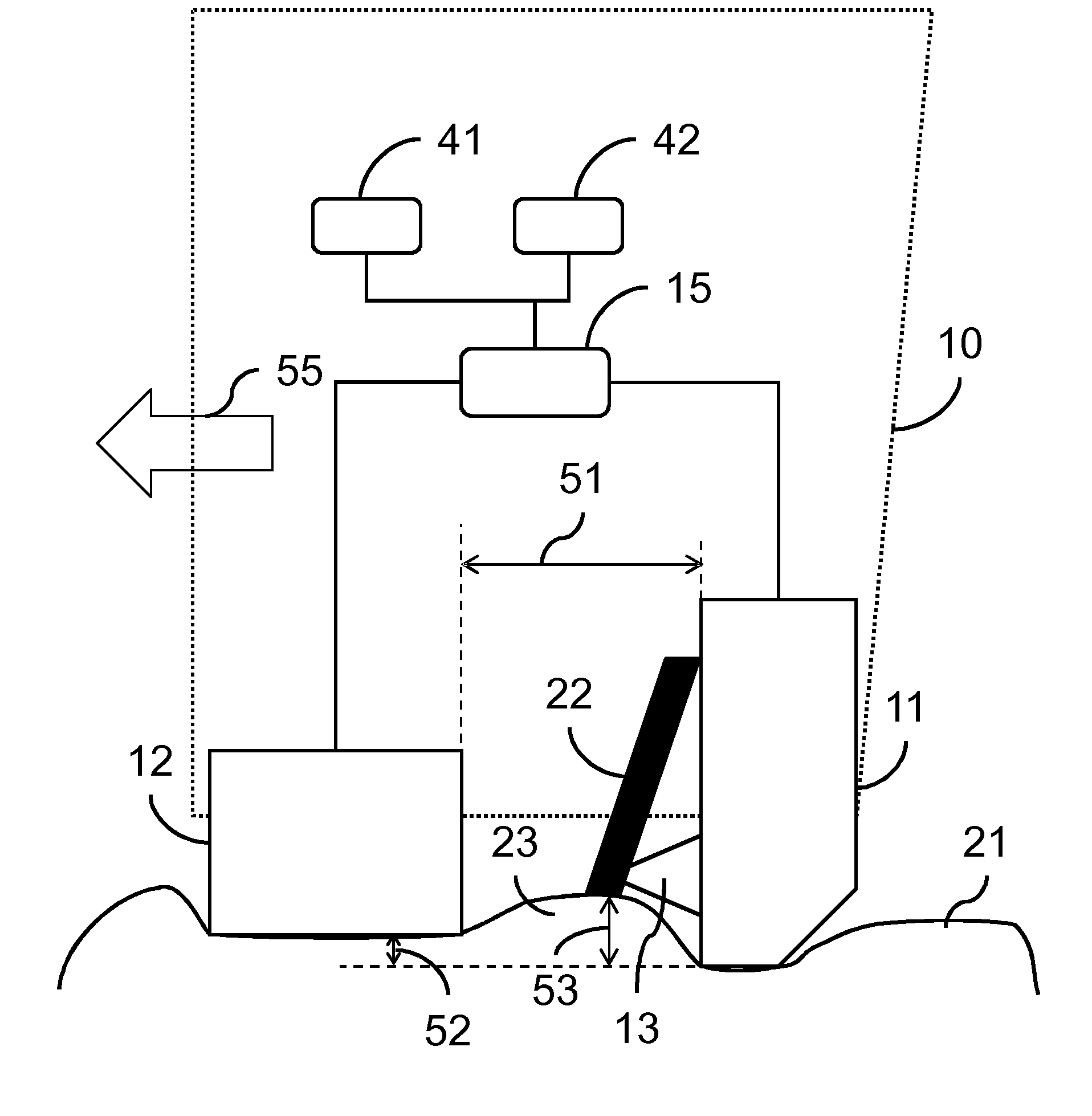
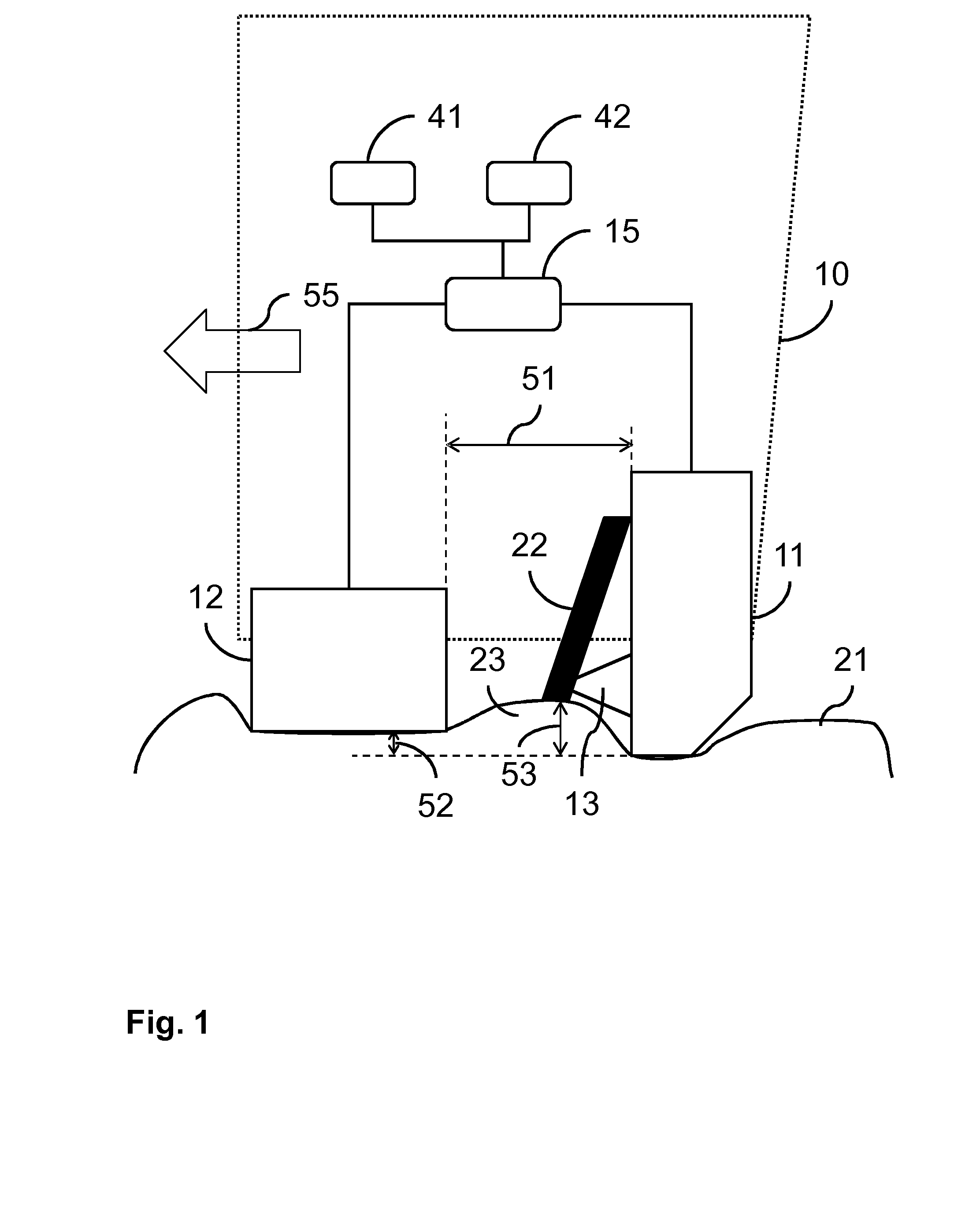
The invention is a hair cutting device that aims to improve skin closeness and reduce irritation. The device uses a slit with optimized dimensions to achieve this balance. The slit size is determined based on the distance between the skin stretcher and the cutter unit, while exposure is measured between the skin-contact surface and the stretcher surface. The device also has a light-based hair detector to selectively target the hairs instead of scanning larger areas. If the skin dome height is high, the slit dimensions can be adjusted to reduce irritation. Additionally, a pressure sensor can be used to adjust the slit dimensions based on the pressure exerted on the stretcher surface. Overall, the invention provides a better skin experience during hair cutting.

Problems solved by technology

When the skin properties are such that the skin dome height is larger than usual, a decrease of the slit size reduces the skin dome height and the irritation caused by the hair cutting laser beam hitting the skin.
In principle, also moving both parts is an option, but this would require a more complex construction of the device from a mechanical point of view.

Method used


Image

  • Hair cutting device
  • Hair cutting device
  • Hair cutting device

Examples


Embodiment Construction

[0022]FIG. 1 schematically shows a cross section of a hair cutting device10 according to the invention. The hair cutting device 10 comprises a cutter unit, here in the form of an optical blade 11, optionally with a tapered end as also described in the international patent application published as WO 2011 / 010246. The optical blade 11 comprises optical elements like mirrors, reflectors and lenses for directing a hair cutting laser beam 13 through an exit window of the optical blade 11 and focusing the hair cutting laser beam 13 in a focal point near the skin surface 21. The optical blade 11 preferably also comprises the light source for the hair cutting laser beam 13. The same or additional optical elements may also be used by a light based hair detector which is used for distinguishing hairs 22 from skin 21. The hair detector and the hair cutting laser may both use the same light source, possibly at a different intensity. Alternatively, separate light sources may be provided for dete...


PUM


Abstract

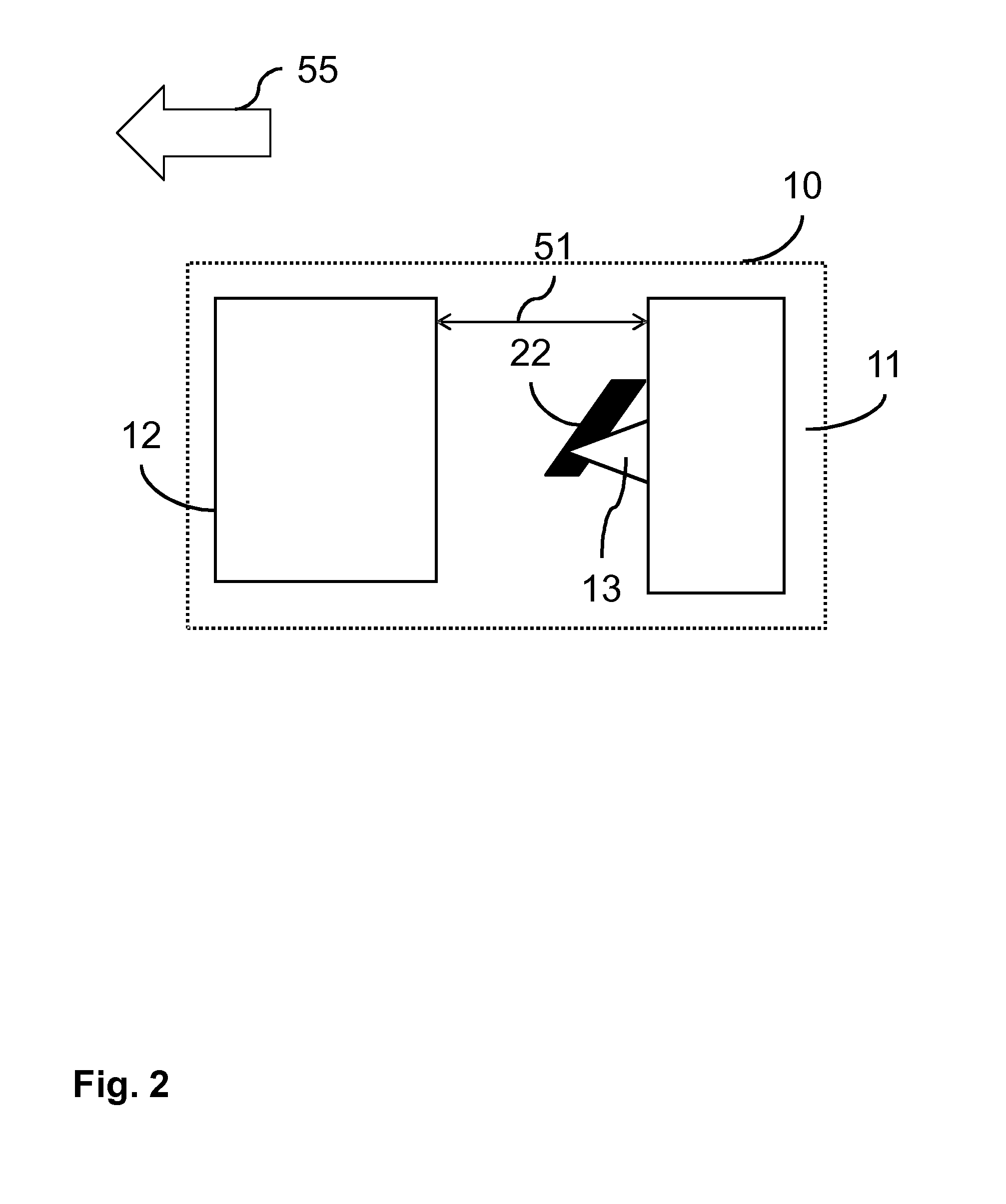
A hair cutting device (10) is provided comprising a cutter unit (11), a skin stretcher (12) and slit adapting means. The cutter unit (11) comprises a skin-contact surface for dragging over a skin surface (21) in a shaving direction (55), a front surface arranged in front of the skin-contact surface in the shaving direction (55), and a laser beam exit window arranged in the front surface for allowing a hair cutting laser beam (13) to cut a hair (22) near the skin surface (21) in front of the front surface. The skin stretcher (12) is positioned in front of the cutter unit (11), according to the shaving direction (55), and comprises a stretcher surface for dragging over the skin surface (21) together with the skin-contact surface, such that a skin dome (23) is formed by the skin surface (21) in a slit between the skin stretcher (12) and the cutter unit (11). The slit adapting means are provided for adapting at least one dimension (51, 52, 54) of the slit for controlling a shape of the skin dome (23).

Description

FIELD OF THE INVENTION[0001]This invention relates to a hair cutting device comprising cutter unit and a skin stretcher. The cutter unit comprises a skin-contact surface for dragging over a skin surface in a shaving direction, a front surface arranged in front of the skin-contact surface in the shaving direction, and a laser beam exit window arranged in the front surface for allowing a hair cutting laser beam to cut a hair near the skin surface in front of the front surface. The skin stretcher is positioned in front of the cutter unit, according to the shaving direction, and comprises a stretcher surface for dragging over the skin surface together with the skin-contact surface.BACKGROUND OF THE INVENTION[0002]Such a hair cutting device is, e.g., known from the international patent application published as WO 2011 / 010246. Said patent application describes a hair cutting device for cutting hair near skin of a human or animal body part. An optical blade, embodying the functionality of ...

Claims


Application Information

Patent Timeline
Patent Type & Authority Applications(United States)
IPC IPC(8): B26B21/40
CPCB26B21/405B26B19/388B26B21/4056A61B18/20B26B19/00
Inventor DAMKAT, CHRISUZUNBAJAKAVA, NATALIA EDUARDAUNACIUHU, CALINAVEENSTRA, GEERTKOOIKER, HARMEN
Owner KONINKLIJKE PHILIPS ELECTRONICS NV
Learn More