Door locking device

a door locking and door technology, applied in the field can solve the problems of poor operation, slow operation, and high cost of door locking devices, and achieve the effects of enhancing operability, low cost, and low cos

Active Publication Date: 2014-11-27
U SHIN LTD
View PDF8 Cites 5 Cited by
  • Summary
  • Abstract
  • Description
  • Claims
  • Application Information

AI Technical Summary

Benefits of technology

[0033]When the inner door handle is operated in a door locked state, the door can be opened by operating only the first link. Accordingly, an operation stroke of the inner door handle can be suppressed to a value within a range more suitable for enhancing operability. Further, it is unnecessary to operate the locking mechanism (second link) before operating the latch mechanism and hence, required accuracy in parts and required accuracy in assembly are not so high and hence, the door locking device can be manufactured at a low cost.

Problems solved by technology

Accordingly, it is necessary to make a rotational range (stroke) of the inner door handle large thus giving rise to a drawback that operability is poor (the slow operation feeling).
In the door locking device disclosed in patent literature 1, to change over the locking mechanism to an unlock state from a lock state and, thereafter, to operate the latch mechanism by operating the inner door handle, the locking mechanism and the latch mechanism are required to satisfy high part accuracy and assembly accuracy thus also giving rise to a possibility that the door locking device becomes expensive.

Method used


Image

  • Door locking device
  • Door locking device
  • Door locking device

Examples


Embodiment Construction

[0047]Hereinafter, an embodiment of the present invention is explained by reference to attached drawings. In the explanation made hereinafter, terms which indicate specific direction and positions (terms which include “up”, “down”, “side”, “end”, for example) are used when necessary. However, these terms are used for facilitating the understanding of the present invention by reference to drawings, and the technical scope of the present invention is not limited by meanings which these terms have. Further, the following description substantially exemplifies examples and does not intend to limit the present invention, objects to which the present invention is applied or the use of the present invention.

(1. Overall Structure)

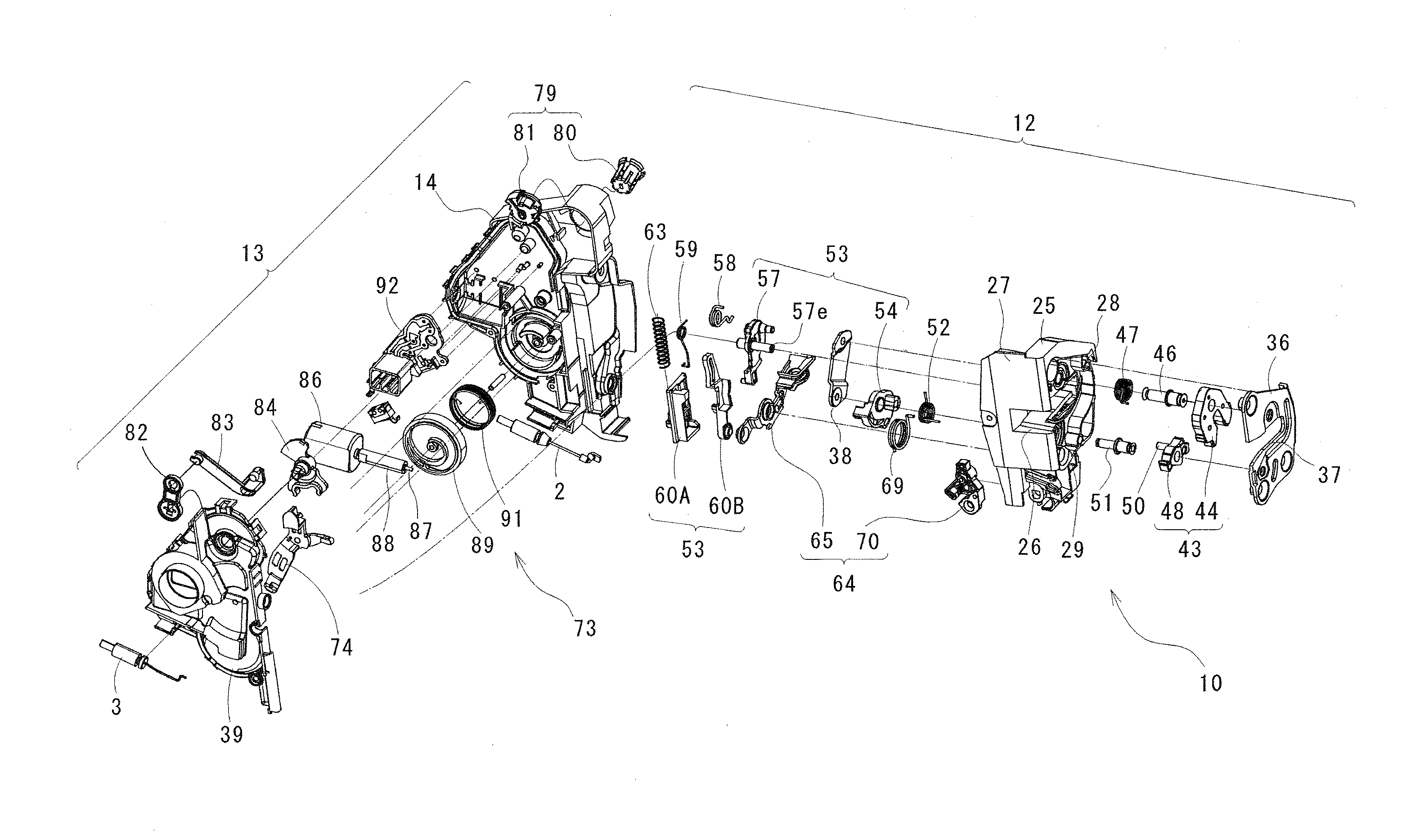
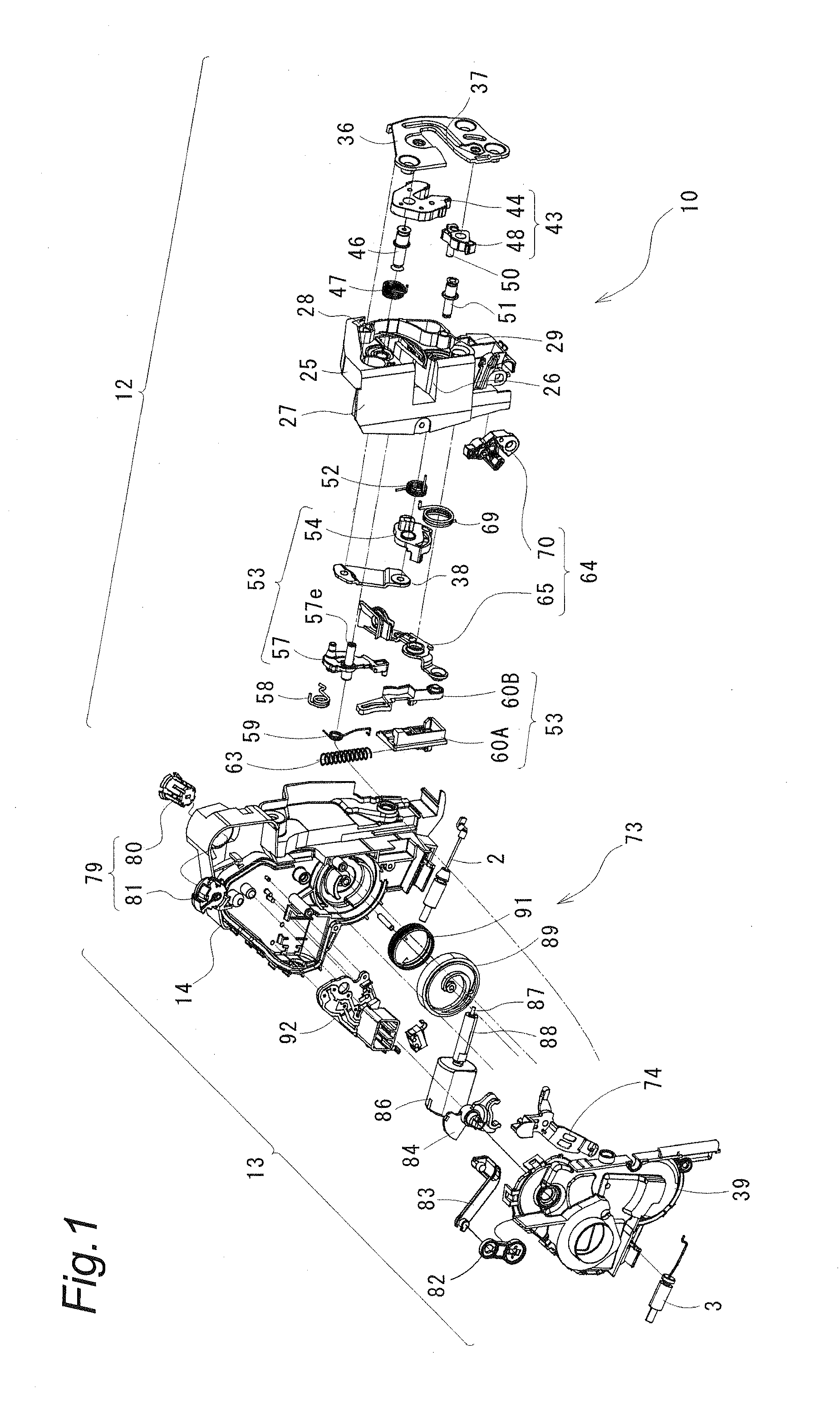
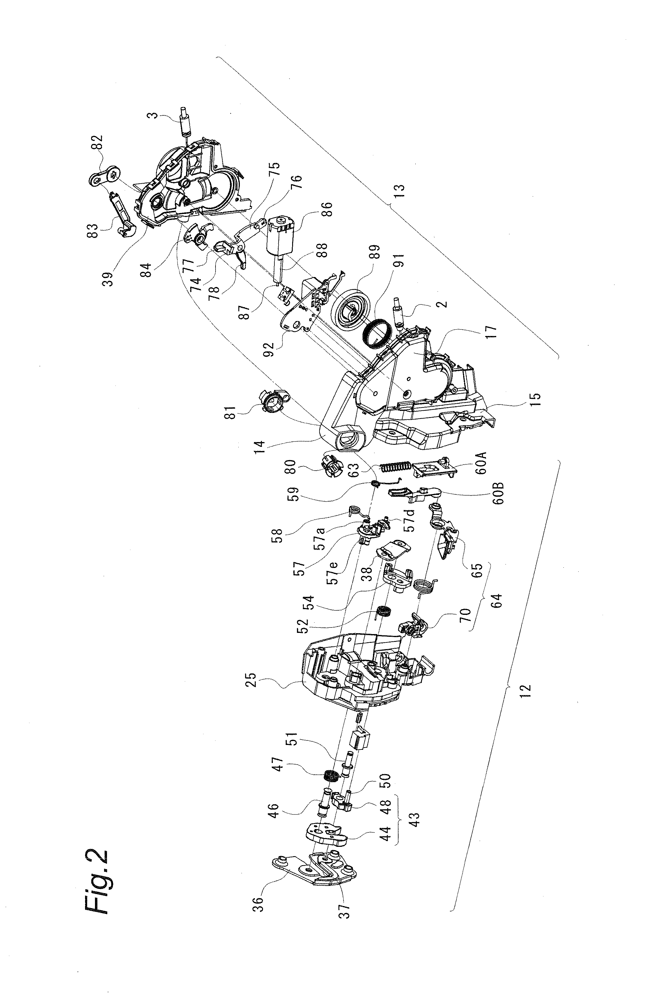
[0048]FIG. 1 and FIG. 2 show a door locking device 10 according to this embodiment. The door locking device 10 is arranged in the inside of a door mounted on a vehicle body not shown in the drawing. In a state where the door is closed with respect to the vehicle bod...


PUM


Abstract

Provided is a door locking device which includes: a latch mechanism with which a striker is engageable or from which the striker is disengageable; a first link which operates the latch mechanism in an interlocking manner with an inner door handle so as to release the striker; a second link which is movable between an unlocked position where the second link is operated in an interlocking manner with the first link and a locked position where the second link is not operated in an interlocking manner with the first link, and operates the latch mechanism in an interlocking manner with an outer handle by way of the first link in the unlocked position so as to release the striker; and a locking lever which changes over the second link between the unlocked position and the locked position.

Description

BACKGROUND OF THE INVENTION[0001]1. Field of the Invention[0002]The present invention relates to a door locking device.[0003]2. Description of Related Art[0004]Conventionally, as a door locking device mounted on a door of a vehicle, there has been known a door locking device having an override function. The override function is a function of, at the time of opening the door by operating an inner door handle mounted on the door inside a vehicle, opening the door due to an operation of the inner door handle one time even when the door locking device is in a locked state.[0005]JP-A-2009-203738 (patent literature 1) discloses a door locking device having an override function. The door locking device includes: an engaging portion by which an inner lever connected to the inner door handle operates a locking mechanism; and a link operating portion which operates a latch mechanism. By operating the inner door handle one time, a locked state of the locking mechanism is released by operating ...

Claims


Application Information

Patent Timeline
Patent Type & Authority Applications(United States)
IPC IPC(8): E05C3/12
CPCE05C3/12E05B81/06E05B81/16E05B83/36Y10S292/23Y10T292/1047Y10T292/1076
Inventor AKAGI, NOBUYA
Owner U SHIN LTD
Why Eureka
Try Eureka