Touch Type Input Termnal

a technology of input terminal and input terminal, which is applied in the direction of instruments, electrical/magnetic measurement arrangement, electric/magnetic position measurement, etc., can solve the problem of not being able to accept more diverse operation inputs

Active Publication Date: 2014-11-27
MURATA MFG CO LTD
View PDF4 Cites 19 Cited by
  • Summary
  • Abstract
  • Description
  • Claims
  • Application Information

AI Technical Summary

Benefits of technology

[0018]According to the present invention, it is possible to implement a touch type input terminal capable of carrying out various operation inputs.

Problems solved by technology

For this reason, it is impossible to accept more various operation inputs.

Method used


Image

  • Touch Type Input Termnal
  • Touch Type Input Termnal
  • Touch Type Input Termnal

Examples


first embodiment

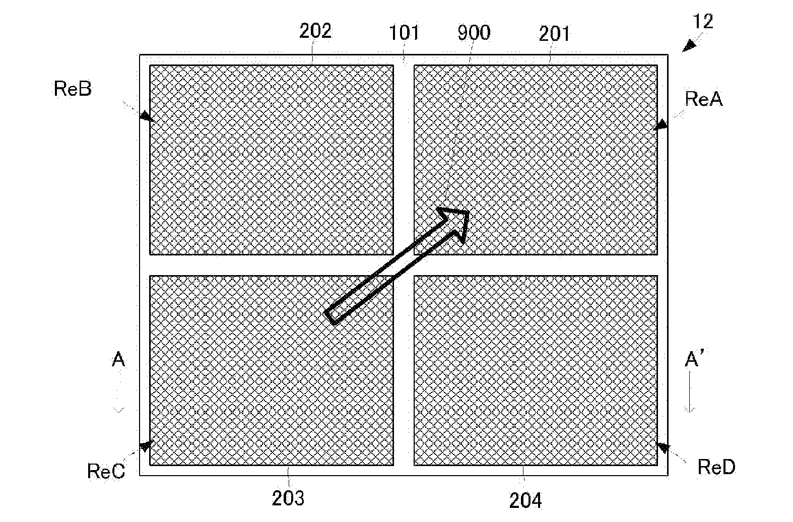
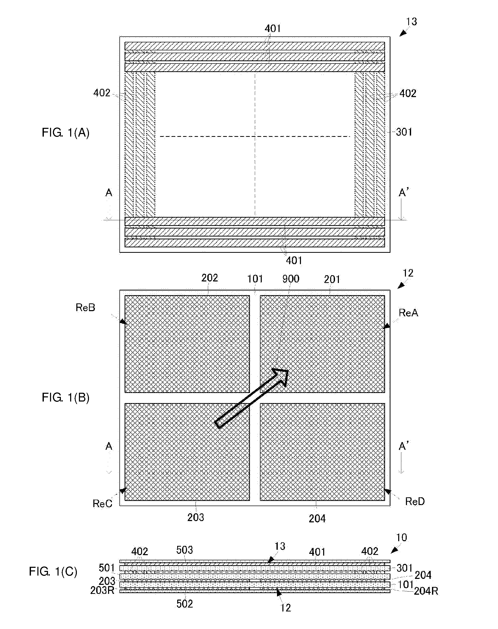
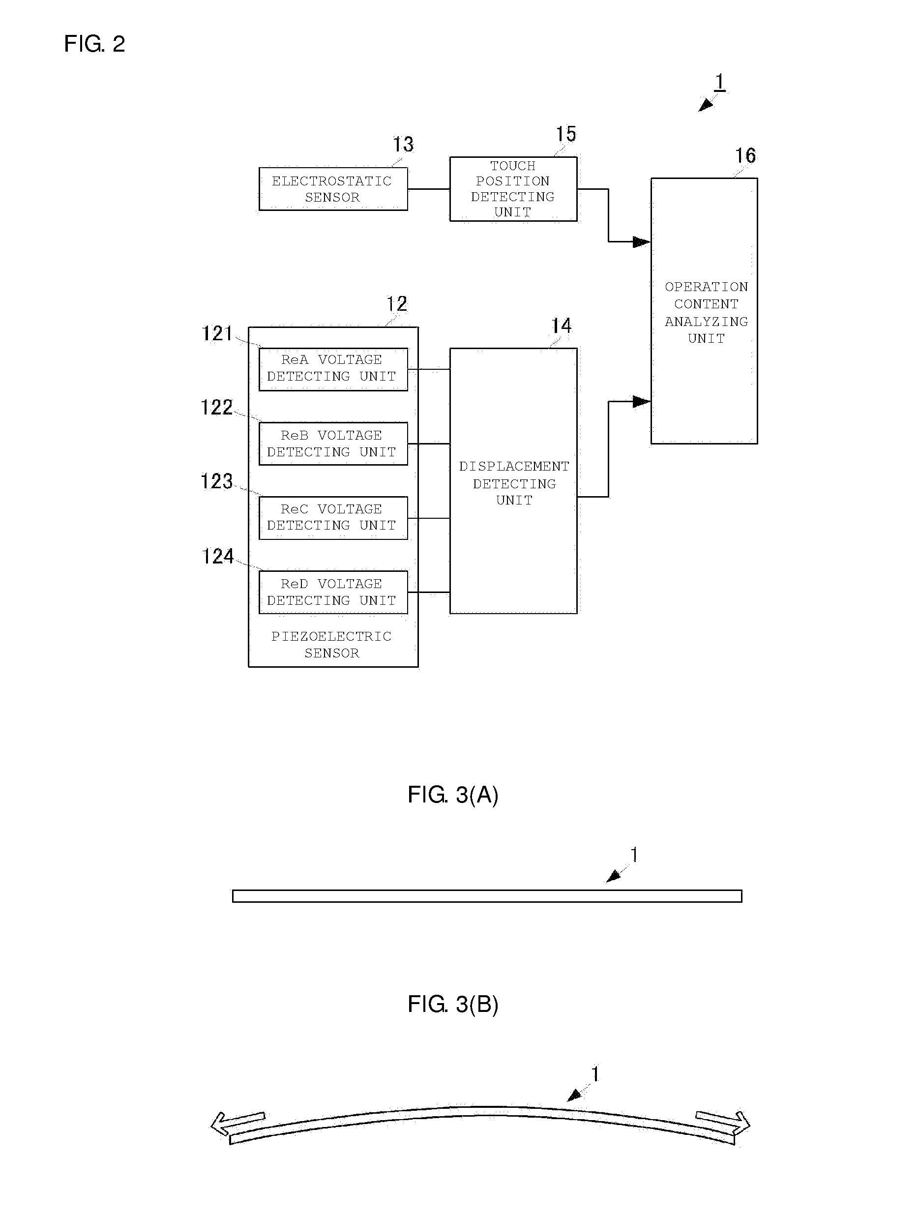
[0067]Next, a detection concept of the bend or twist according to the present embodiment will be described in more detail. FIGS. 3(A) and 3(B) are conceptual views showing the case in which the touch type input terminal 1 is bent, and FIG. 3(A) is a side view showing a state brought before the bend and FIG. 3(B) is a side view showing a bending state. FIGS. 3(A) and 3(B) show the case in which the touch type input terminal 1 is bent in a longitudinal direction. In FIGS. 3(A) and 3(B), moreover, an upper side of FIGS. 3(A) and 3(B) correspond to the operation surface side of the touch type input terminal 1. FIGS. 4(A) and 4(B) are conceptual views showing the case in which the touch type input terminal 1 is twisted, FIG. 4(A) is a perspective view showing a state brought before the twist and FIG. 4(B) is a perspective view showing a twisting state. For easy understanding of the drawings and principle, FIGS. 3(A), 3(B), 4 (A) and 4 (B) show the structure of the touch type input termin...

second embodiment

[0085]With this structure, bend or twist can be detected as follows. FIG. 7 is a table showing an example of a voltage distribution in a state in which the touch type input terminal 1A according to the present invention is bent and a state in which the touch type input terminal 1A is twisted.

(Bending Displacement Detection)

[0086]In the case in which a bending displacement is zero, that is, external force for generating the bend is not applied to the touch type input terminal 1A, the base substrate 501 of the touch type input terminal 1A is brought into a state in which the main surface is flat. In this case, the piezoelectric film 101A of the piezoelectric sensor 12A neither extends nor contracts and an output voltage from the piezoelectric sensor 12A is not changed by the bending displacement. For example, if the detection voltage is set to be 0[V] in this state, all of the detection voltage V(ReA) output from the ReA voltage detecting unit 121, the detection voltage V(ReB) output ...


PUM


Abstract

A touch type input terminal that includes a base substrate, a piezoelectric sensor and an electrostatic sensor which are flat membrane-shaped, respectively. The electrostatic sensor includes a plurality of segment electrodes on a first main surface of a base film and a plurality of common electrodes on a second main surface. The piezoelectric sensor includes a piezoelectric film formed of PLLA drawn uniaxially. Displacement detecting electrodes are formed on a third main surface of the piezoelectric film so as to divide the third main surface into four portions. Displacement detecting electrodes are formed on a fourth main surface of the piezoelectric film so as to be opposed to the displacement detecting electrodes on the third main surface.

Description

CROSS REFERENCE TO RELATED APPLICATIONS[0001]The present application is a continuation of International application No. PCT / JP2013 / 053311, filed Feb. 13, 2013, which claims priority to Japanese Patent Application No. 2012-030374, filed Feb. 15, 2012, the entire contents of each of which are incorporated herein by reference.FIELD OF THE INVENTION[0002]The present invention relates to a touch type input terminal for detecting a position in which an operation input is carried out with a finger or the like.BACKGROUND OF THE INVENTION[0003]Various touch type input terminals (devices) for detecting a touch position of an operation surface by an operator are conventionally devised. For example, the touch type input device disclosed in Patent Document 1 has a structure in which a plate-shaped electrostatic capacity detection type touch sensor and a plate-shaped pressure sensitive sensor are superimposed on each other. With the structure, the touch type input device disclosed in the Patent D...

Claims


Application Information

Patent Timeline
Patent Type & Authority Applications(United States)
IPC IPC(8): G06F3/041G01B7/14G01B7/00
CPCG06F3/041G06F2203/04102G01B7/14G01B7/003G01L1/16G06F3/03G06F3/0416G06F3/0445G06F3/0446G06F2203/04106
Inventor ANDO, MASAMICHI
Owner MURATA MFG CO LTD
Why Eureka
Try Eureka