
Potentiostatic electrolytic gas sensor

a gas sensor and electrolytic technology, applied in the field of potentiostatic electrolytic gas sensors, can solve the problems of high index accuracy, inability to perform gas detection with high reliability, and inability to accurately detect gas, so as to reduce the occurrence of index errors, prevent or reduce the occurrence, and achieve accurate gas sensitivity

Inactive Publication Date: 2016-09-08
RIKEN KEIKI KK
View PDF5 Cites 7 Cited by
  • Summary
  • Abstract
  • Description
  • Claims
  • Application Information

AI Technical Summary

Benefits of technology

The present invention is related to a potentiostatic electrolytic gas sensor with high gas detection accuracy and reliability regardless of the composition of the gas being detected. The technical effects of this invention include the use of a specific metal for the lead member(s) of the working electrode and counter electrode, which prevents or reduces the occurrence of detrimental effects caused by miscellaneous gases or produced gas in the environmental atmosphere. Additionally, the reference electrode lead member is made of the specific metal, which ensures stable electrode potential and accurate gas sensitivity regardless of the gas composition being detected. These features allow for high gas detection reliability and performance regardless of the gas composition being detected.

Problems solved by technology

However, the potentiostatic electrolytic gas sensors have the problem that gas detection with high reliability could not be performed for the reason that the reference electrode or the lead members is formed of platinum.
Thus, in the potentiostatic electrolytic gas sensors having the reference electrode made of platinum, the potential of the reference electrode being a reference varies depending on the composition of the object gas, thus impairing accurate gas sensitivity, that is, high index accuracy.
Thus, in the potentiostatic electrolytic gas sensors having the lead members made of platinum, various detriments occur by the effect of the miscellaneous gases contained in the environmental atmosphere (object gas) in the space to be detected, thus impairing accurate gas sensitivity, that is, high index accuracy.
This causes an index error in the potentiostatic electrolytic gas sensors.
Thus, since the electrode potential of the reference electrode as a reference varies, an appropriate voltage cannot be applied to the working electrode.
In this case, an index error occurs, and high index accuracy cannot be obtained thereby.

Method used


Image

  • Potentiostatic electrolytic gas sensor
  • Potentiostatic electrolytic gas sensor
  • Potentiostatic electrolytic gas sensor

Examples


experimental example 1

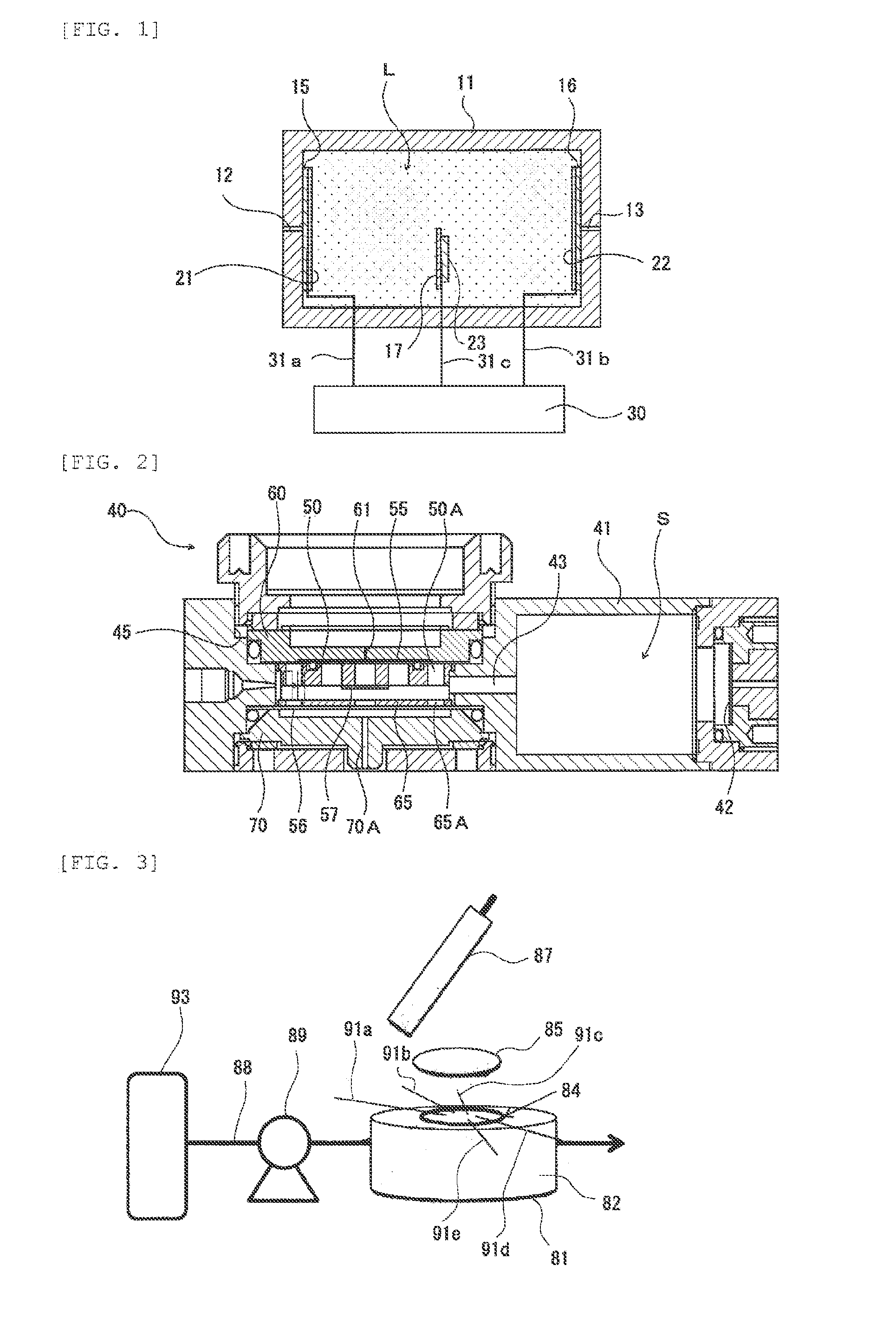
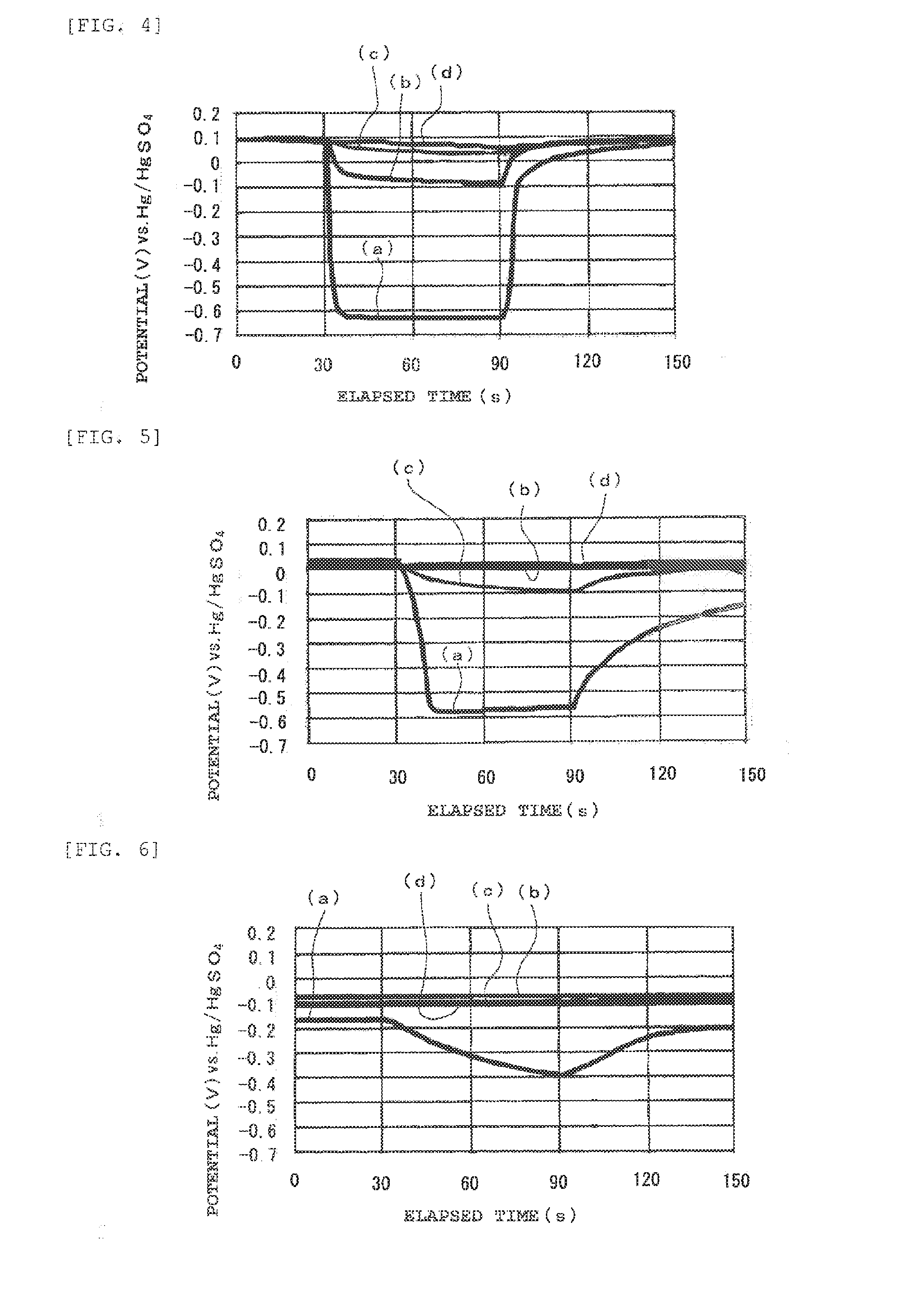
[0207]An experiment device (hereinafter also called “experiment device (1)”) having a structure shown in FIG. 3 was manufactured.

[0208]The experiment device (1) was provided with a container 81 in the shape of a cylinder with a bottom, which was formed with a gas inlet through hole and a gas outlet through hole at a peripheral surface 82. A circular porous PTFE membrane (trade name: “FX-030” (made by Sumitomo Electric Fine Polymer, Inc.)) 84 was attached to the container 81 with a double-sided adhesive tape so as to close an opening. On the top surface (top surface in FIG. 3) of the porous PTFE membrane 84, five kinds of metal wires 91a to 91e were disposed such that one end of each of the metal wires 91a to 91e was situated above the opening of the container 81, and a piece of circular filter paper 85 that was impregnated with a sulfuric acid having a concentration of 18N was disposed. That is to say, the five kinds of metal wires 91a to 91e were caught between the porous PTFE memb...

experimental example 2

[0218]A bipolar experiment device (hereinafter also called “experiment device (2)”) having working electrodes 103 and a counter electrode 104 was manufactured as shown in FIG. 9.

[0219]The experiment device (2) included a casing 100 accommodating an electrolytic solution L. A gas-permeable hydrophobic membrane 102 was placed sc as to cover a gas supply controller that was constituted of a gas inlet through hole 101 formed in the casing 100, from inside. The five working electrodes 103 were provided on the gas-permeable hydrophobic membrane 102 on the side of the electrolytic solution L. There was provided a mercury sulfate electrode as the counter electrode 104 in the casing 100, together with the five working electrodes 103, a distance away from the five working electrodes 103. As an internal liquid of the mercury sulfate electrode, a potassium sulfate (K2SO4) solution having a concentration of 0.35 mol / L was used.

[0220]In this experiment device (2), as the gas-permeable hydrophobic...

experimental example 3

[0227]An experiment device (hereinafter also called “experiment device (3)”) that had the same structure as the experiment device (2) other than provision of four working electrodes described below was manufactured.

[0228]The four working electrodes constituting the experiment device (3) were each made of a disk-shaped electrode catalyst layer having a diameter of 4 mm provided in a gas-permeable hydrophobic membrane. The four working electrodes included a platinum black electrode made of platinum black, a platinum monoxide electrode made of a platinum oxide (II) (PtO), a ruthenium electrode made of ruthenium (Ru), and an iridium electrode made of iridium (Ir). To be more specific, the platinum black electrode was formed by firing platinum black together with a binder at a firing temperature of 320° C., as in the case of the experimental example 2. The platinum monoxide electrode was formed by firing a platinum monoxide (II) together with a binder at a firing temperature of 320° C. T...


PUM

PropertyMeasurementUnit
thicknessaaaaaaaaaa
porosityaaaaaaaaaa
thicknessaaaaaaaaaa

Abstract

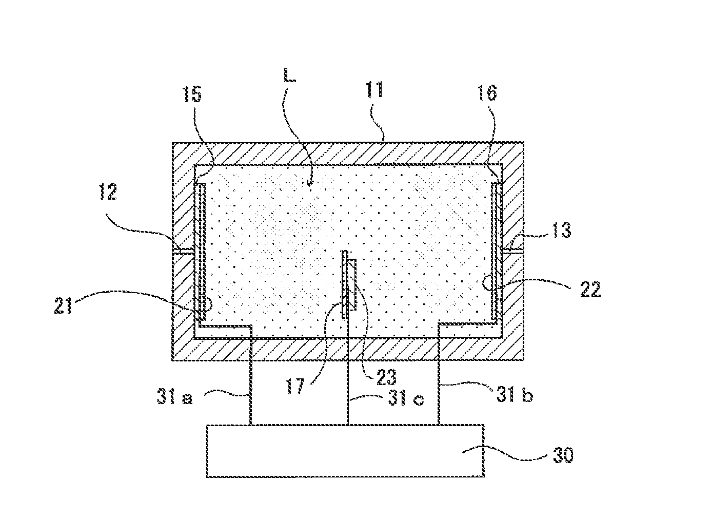
Provided is a potentiostatic electrolytic gas sensor that can perform gas detect with high reliability. In the potentiostatic electrolytic gas sensor, a working electrode and a counter electrode are provided inside a casing with an electrolytic solution interposed therebetween. A working electrode lead member is drawn out of the casing at one end, and electrically connected to the working electrode at the other end. A counter electrode lead member is drawn out of the casing at one end and electrically connected to the counter electrode at the other end. The potentiostatic electrolytic gas sensor is characterized in that at least one of the working electrode lead member and the counter electrode lead member is made of a metal selected from gold, tungsten, niobium, and tantalum.

Description

TECHNICAL FIELD[0001]The present invention relates to a potentiostatic electrolytic gas sensor.BACKGROUND ART[0002]There are conventionally known potentiostatic electrolytic gas sensors that have a casing for containing an electrolytic solution and a gas-permeable hydrophobic membrane placed over a window formed in the casing. An object gas containing a gas to be detected is permeable through the gas-permeable hydrophobic membrane (for example, refer to Patent Literature 1). The potentiostatic electrolytic gas sensors of a certain type have a working electrode formed on the gas-permeable hydrophobic membrane on the side of the electrolytic solution, a counter electrode disposed a certain distance away from the working electrode, and a reference electrode disposed away from each of the working electrode and the counter electrode. The potentiostatic electrolytic gas sensor is configured so as to control by a potentiostat to produce a certain potential difference between the working el...

Claims


Application Information

Patent Timeline
Patent Type & Authority Applications(United States)
IPC IPC(8): G01N27/404G01N27/49
CPCG01N27/49G01N27/404
Inventor UESUGI, SHINJIUCHIKOSHI, SHOUICHIDAIKUHARA, KENJI
Owner RIKEN KEIKI KK
Learn More