
Sheet conveying apparatus, image forming apparatus, sheet conveying distance calculation apparatus and sheet length calculation apparatus

a technology of conveying apparatus and calculation apparatus, which is applied in the direction of electrographic process apparatus, thin material handling, instruments, etc., can solve the problems of inability to accurately measure the length of the sheet, complicated apparatus structure, etc., and achieve the effect of accurate obtaining the conveying distance of the sheet and simple structur

Active Publication Date: 2014-11-27
RICOH KK
View PDF3 Cites 1 Cited by
  • Summary
  • Abstract
  • Description
  • Claims
  • Application Information

AI Technical Summary

Benefits of technology

The present invention provides a sheet conveying apparatus that can accurately determine the distance a sheet is conveyed without confusion. This apparatus has a simple structure, making it easy to use.

Problems solved by technology

There are two main reasons for causing a registration error occurring in both-sides printing, including registration error in the lateral and the vertical directions, and a skew error between a sheet and an image.
Further, for an image forming apparatus including a heat fixing device, an image size error caused by expansion and contraction of the sheet is also a reason for registration error occurring in both-sides printing.
However, for the length measuring means disclosed in Patent Document 1, the speed detection means for detecting the conveying speed of the object to be transferred is necessary so that the structure of the apparatus becomes complicated.
Further, as the length measuring roller does not have a driving force, there may be a case where slipping, looseness or the like is generated between the recording sheet and the length measuring roller so that it is not possible to accurately measure the sheet length.

Method used


Image

  • Sheet conveying apparatus, image forming apparatus, sheet conveying distance calculation apparatus and sheet length calculation apparatus
  • Sheet conveying apparatus, image forming apparatus, sheet conveying distance calculation apparatus and sheet length calculation apparatus
  • Sheet conveying apparatus, image forming apparatus, sheet conveying distance calculation apparatus and sheet length calculation apparatus

Examples


Embodiment Construction

[0033]The invention will be described herein with reference to illustrative embodiments. Those skilled in the art will recognize that many alternative embodiments can be accomplished using the teachings of the present invention and that the invention is not limited to the embodiments illustrated for explanatory purposes.

[0034]It is to be noted that, in the explanation of the drawings, the same components are given the same reference numerals, and explanations are not repeated.

(Structure of Sheet Conveying Apparatus)

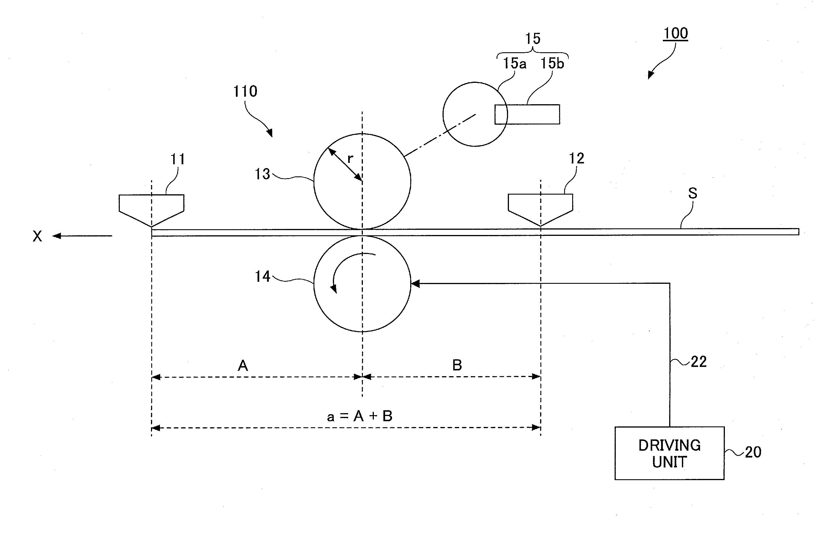
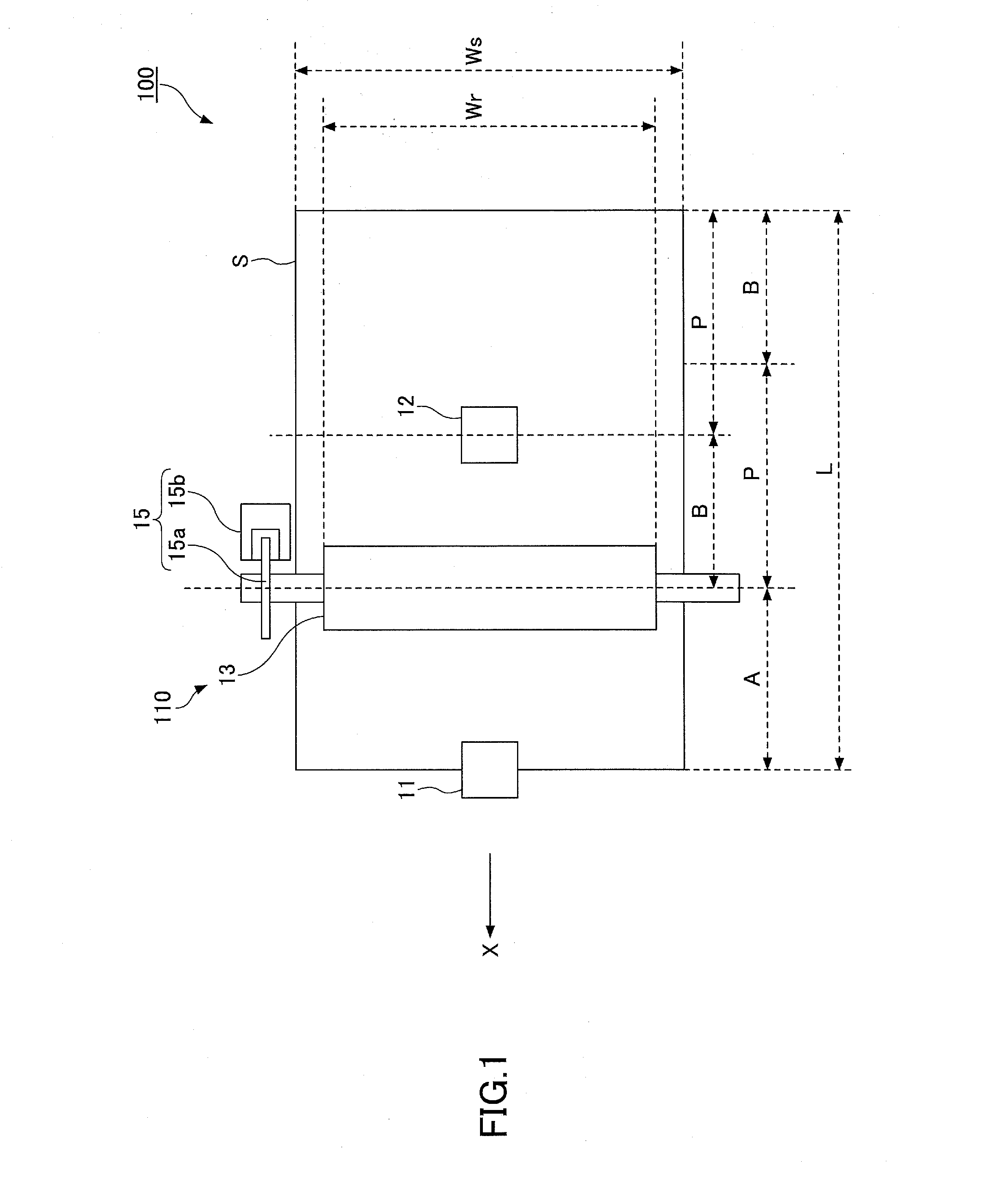
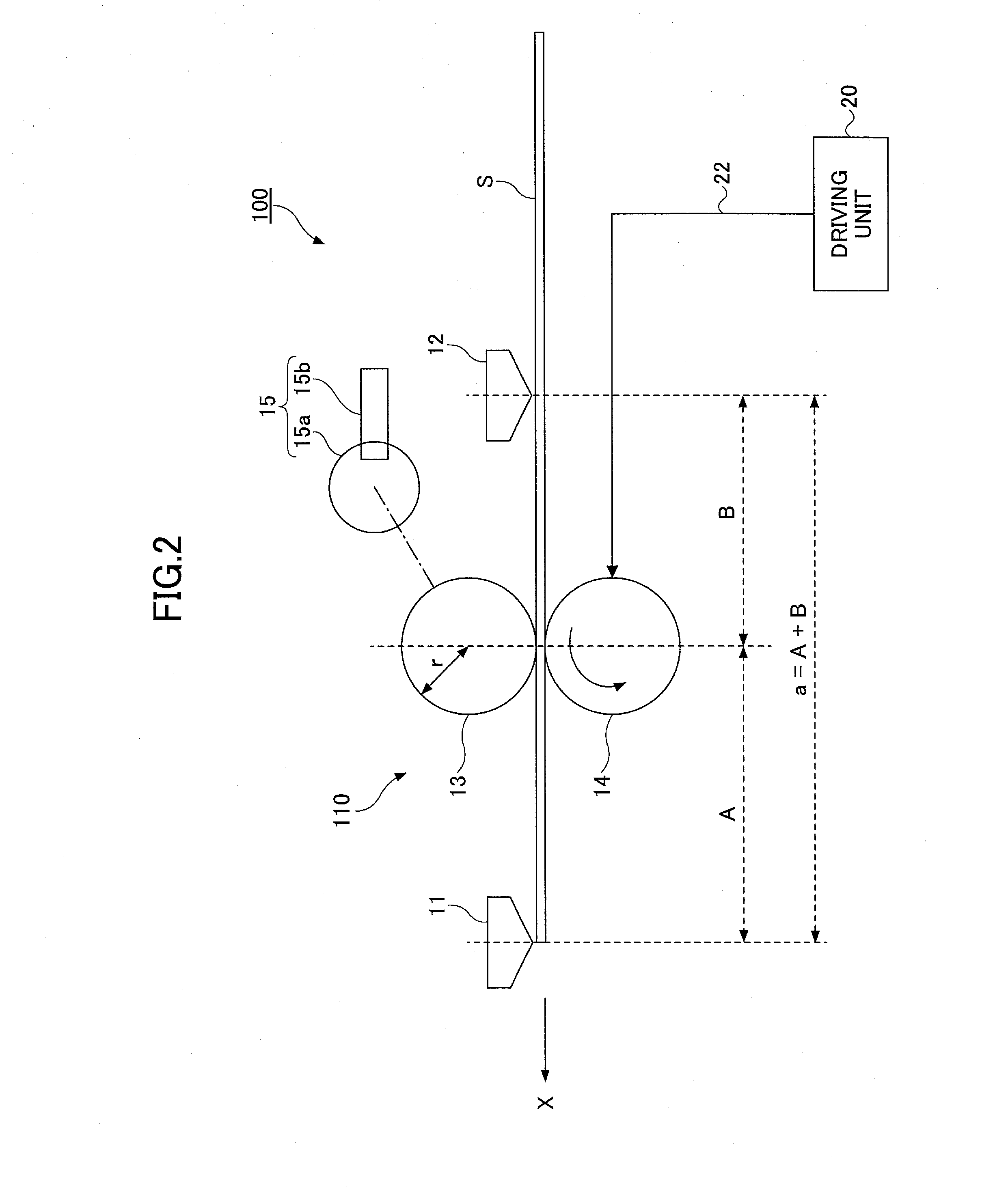
[0035]FIG. 1 and FIG. 2 are views showing an outline constitution of a sheet conveying apparatus 100 of the embodiment. FIG. 1 is a plan view schematically showing an example of a structure of the sheet conveying apparatus 100 and FIG. 2 is a cross-sectional view schematically showing an example of a structure of the sheet conveying apparatus 100.

[0036]The sheet conveying apparatus 100 includes a sheet conveying unit 110 provided on a conveying path of a sheet S, a start ...


PUM


Abstract

A sheet conveying apparatus includes a sheet conveying unit that conveys a sheet including a drive roller, a driven roller, and a rotary encoder provided on a rotational axle of one of the drive roller and the driven roller; a conveying amount measuring unit that measures a conveying amount of the sheet; a first detection unit positioned downstream of the sheet conveying unit, the first detection unit being positioned apart from the drive roller and the driven roller not to overlap with the drive roller and the driven roller in the conveying direction; a second detection unit positioned upstream of the sheet conveying unit; and a conveying distance calculation unit that calculates a conveying distance of the sheet based on the measured result by the conveying amount measuring unit and the detected results detected by the first detection unit and the second detection unit.

Description

CROSS-REFERENCE TO RELATED APPLICATIONS[0001]This application is a continuation application of U.S. patent application Ser. No. 13 / 559,837 filed on Jul. 27, 2012, which claims the benefit of priority of Japanese Priority Application No. 2011-172318 filed on Aug. 5, 2011, and Japanese Priority Application No. 2012-123115 filed on May 30, 2012, where the entire contents of all of these applications are incorporated herein by reference.BACKGROUND OF THE INVENTION[0002]1. Field of the Invention[0003]The present invention relates to a sheet conveying apparatus, an image forming apparatus, a sheet conveying distance calculation apparatus and a sheet length calculation apparatus.[0004]2. Description of the Related Art[0005]In a commercial printing business, Print on Demand (POD) by an image forming apparatus using electrophotography instead of using an offset printing machine has been provided for printing small lots of data, various types of data or variable data has been increasing. In o...

Claims


Application Information

Patent Timeline
Patent Type & Authority Applications(United States)
IPC IPC(8): G03G15/00B65H7/06B65H5/06
CPCG03G15/6529B65H7/06B65H5/062G03G15/0189G03G15/234G03G15/6561B65H7/20B65H2511/11B65H2513/50B65H2553/51B65H2701/1311B65H2701/1313B65H2511/30B65H2220/01B65H2220/03B65H2220/02B65H5/06B65H7/14G03G15/1615
Inventor NAKURA, MAKOTOKAMIYA, TAKUROTAKAI, SHINGOUEDA, NAOTOUEDA, SATOSHIKOBASHI, AKIRAKUDO, KOICHI
Owner RICOH KK
Features
  • Generate Ideas
  • Intellectual Property
  • Life Sciences
  • Materials
  • Tech Scout
  • Unparalleled Data Quality
  • Higher Quality Content
  • 60% Fewer Hallucinations
Learn More