Upper airway resistance measurement device

a technology measurement device, which is applied in the field of upper airway resistance measurement device, can solve the problems of affecting the use of known methods, estimating the upper airway resistance of mechanically ventilated patients who spontaneously breathe, and affecting the use of medical devices

Active Publication Date: 2014-11-27
KONINKLIJKE PHILIPS ELECTRONICS NV
View PDF12 Cites 8 Cited by
  • Summary
  • Abstract
  • Description
  • Claims
  • Application Information

AI Technical Summary

Benefits of technology

[0008]Accordingly, it is an object of the present invention to provide a method of estimating the upper airway resistance of a patient using a gas delivery system that overcomes the shortcomings of conventional estimation methods, such as those shortcomings presented by non-ideal instrumentation and / or flow leaks.
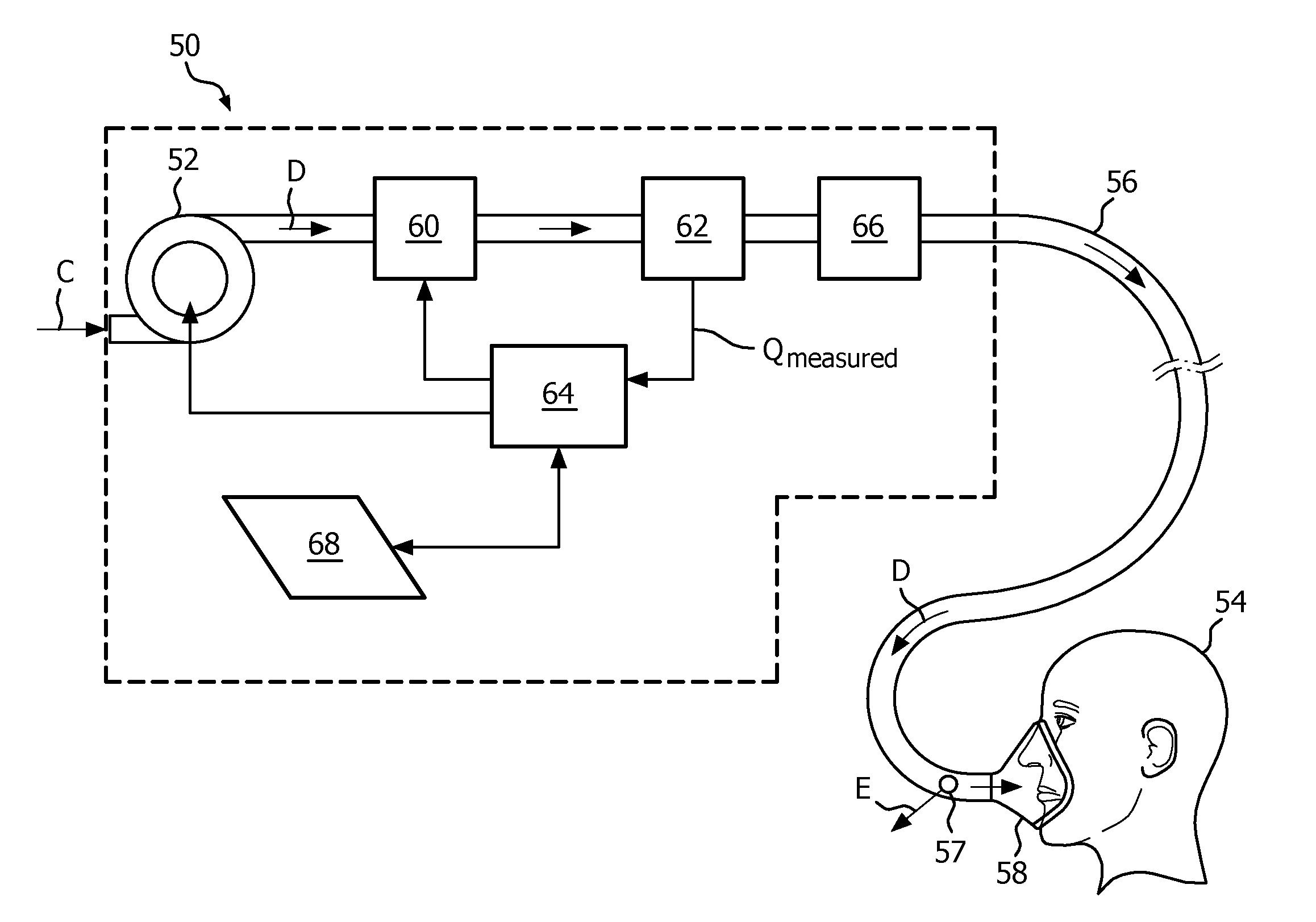
[0009]In one embodiment, the method includes delivering a flow of breathing gas to the patient through the patient circuit of the gas delivery system, superimposing an oscillatory pressure on the flow of breathing gas during an expiratory phase of the patient, determining a first amplitude of an oscillatory component of a gas pressure provided to the patient at the end of the expiratory phase, determining a second amplitude of an oscillatory component of a gas flow provided to the patient at the end of the expiratory phase, determining a first resistance value based on the ratio of the first amplitude to the second amplitude, and determining an upper airway resistance value based on the first resistance value.
[0010]In another embodiment, a gas delivery system is provided that includes a pressure or flow generating system adapted to produce a flow of breathing gas, a patient circuit operatively coupled to the pressure or flow generating system and structured to deliver the flow of breathing gas to the patient, and a controller operatively coupled to the pressure or flow generating system, wherein the controller is structured / programmed to estimate the upper airway resistance of a patient by implementing the method just described.
[0011]These and other objects, features, and characteristics of the present invention, as well as the methods of operation and functions of the related elements of structure and the combination of parts and economies of manufacture, will become more apparent upon consideration of the following description and the appended claims with reference to the accompanying drawings, all of which form a part of this specification, wherein like reference numerals designate corresponding parts in the various figures. It is to be expressly understood, however, that the drawings are for the purpose of illustration and description only and are not intended as a definition of the limits of the invention.

Problems solved by technology

However, estimating upper airway resistance in mechanically ventilated patients who have spontaneous respiratory efforts is rather complex, primarily due to that fact that knowledge of the force applied to the respiratory system is required and the fact that, in ventilated patients who have spontaneous respiratory efforts, that force includes a component related to pressure generated by respiratory muscles (Pmus), which continuously changes during the inflation phase of ventilation.
While there are a number of known methods for patient airway resistance measurement / estimation, including the well known interrupter and forced oscillation techniques, such methods have their drawbacks and limitations.
In particular, such known methods can be adversely affected by non-ideal instrumentation and / or leaks in the patient circuit.

Method used


Image

  • Upper airway resistance measurement device
  • Upper airway resistance measurement device
  • Upper airway resistance measurement device

Examples


Embodiment Construction

[0016]As used herein, the singular form of “a”, “an”, and “the” include plural references unless the context clearly dictates otherwise. As used herein, the statement that two or more parts or components are “coupled” shall mean that the parts are joined or operate together either directly or indirectly, i.e., through one or more intermediate parts or components, so long as a link occurs. As used herein, “directly coupled” means that two elements are directly in contact with each other. As used herein, “fixedly coupled” or “fixed” means that two components are coupled so as to move as one while maintaining a constant orientation relative to each other.

[0017]As used herein, the word “unitary” means a component is created as a single piece or unit. That is, a component that includes pieces that are created separately and then coupled together as a unit is not a “unitary” component or body. As employed herein, the statement that two or more parts or components “engage” one another shal...


PUM


Abstract

A method of estimating the upper airway resistance of a patient using a gas delivery system includes delivering a flow of breathing gas to the patient through the patient circuit of the gas delivery system, superimposing an oscillatory pressure on the flow of breathing gas during an expiratory phase of the patient, determining a first amplitude of an oscillatory component of a gas pressure provided to the patient at an end of the expiratory phase, determining a second amplitude of an oscillatory component of a gas flow provided to the patient at the end of the expiratory phase, determining a first resistance value based on the ratio of the first amplitude to the second amplitude, and determining an upper airway resistance value based on the first resistance value.

Description

CROSS-REFERENCE TO RELATED APPLICATIONS[0001]This patent application claims the priority benefit under 35 U.S.C. §119(e) of U.S. Provisional Application No. 61 / 537,188, filed on Sep. 21, 2011, the contents of which are herein incorporated by reference.BACKGROUND OF THE INVENTION[0002]1. Field of the Invention[0003]The present invention relates to gas delivery systems, such as pressure support systems and other ventilator (invasive or non-invasive) systems, and, more particularly, to a method for estimating the upper airway resistance of a subject using the gas delivery system, and a gas delivery system employing such a method.[0004]2. Description of the Related Art[0005]As is well known in the art, there are numerous situations where it is necessary or desirable to deliver a flow of breathing gas non-invasively to the airway of a patient, i.e., without intubating the patient or surgically inserting a tracheal tube in his or her esophagus. Such therapies are commonly referred to as n...

Claims


Application Information

Patent Timeline
Patent Type & Authority Applications(United States)
IPC IPC(8): A61B5/085A61M16/00
CPCA61M16/0003A61B5/085A61M16/0066A61M2016/0027A61M2016/0039A61M2016/0042A61M2230/46A61M16/0069A61M16/101A61M16/026A61M16/0096A61M16/205A61M2016/0036A61M16/0006
Inventor TRUSCHEL, WILLIAM A.MAHADEVAN, ANANDI
Owner KONINKLIJKE PHILIPS ELECTRONICS NV
Why Eureka
Try Eureka