
System and Method for Virtualized Shared Use Environment with Dynamic IP Address Injection

a virtualized shared use environment and dynamic injection technology, applied in the field of shared or common use systems, can solve the problem of several minutes of time required to initiate a session in this configuration

Inactive Publication Date: 2014-11-27
BAIRD STEVEN LLOYD
View PDF9 Cites 12 Cited by
  • Summary
  • Abstract
  • Description
  • Claims
  • Application Information

AI Technical Summary

Benefits of technology

The invention provides a way to create a shared use environment where multiple servers can be used through a network. This allows operators to access virtual machines quickly after selecting the company software and verifying the user's validity to operate it.

Problems solved by technology

The amount of time required to initiate a session in this configuration took several minutes.
Unfortunately, these early shared use environments required boot partitions similar to the older common use systems.

Method used


Image

  • System and Method for Virtualized Shared Use Environment with Dynamic IP Address Injection
  • System and Method for Virtualized Shared Use Environment with Dynamic IP Address Injection
  • System and Method for Virtualized Shared Use Environment with Dynamic IP Address Injection

Examples


Embodiment Construction

[0037]The following example embodiments and their aspects are described and illustrated in conjunction with apparatuses, methods, and systems which are meant to be illustrative examples, not limiting in scope.

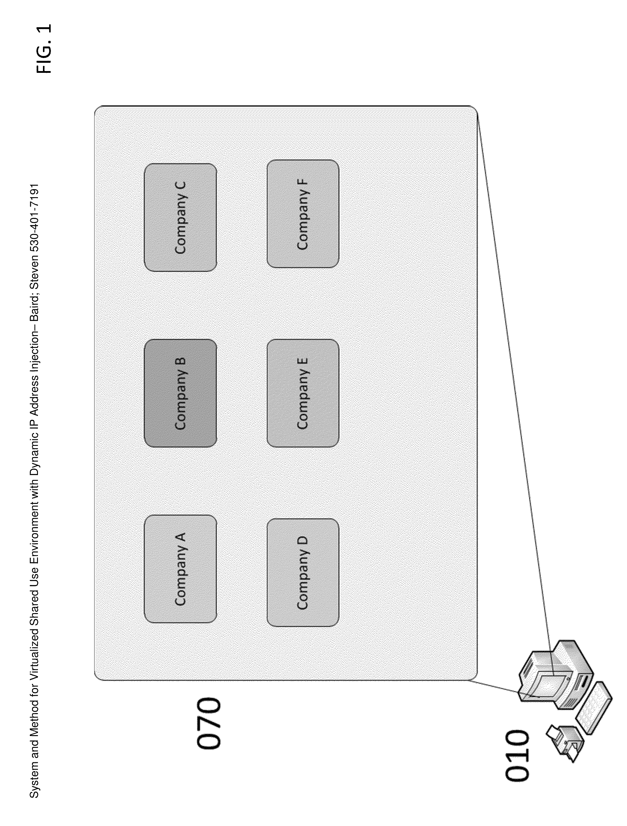
[0038]Menu Presentation—FIG. 1 depicts a menu 070 of company software available to run from edge computing device 010. Selection of the software by the operator will be transmitted to the system control software through the local area network (LAN).

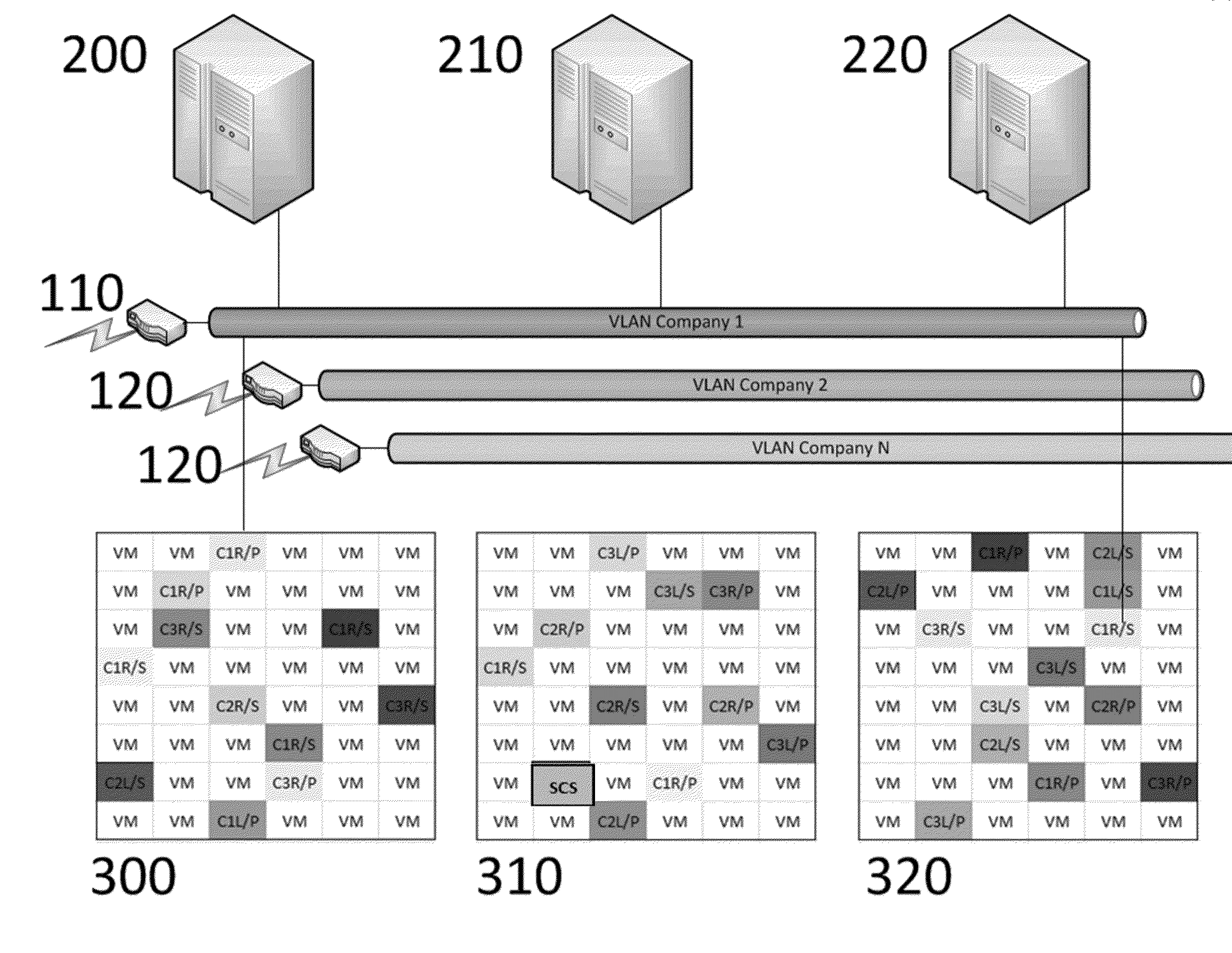
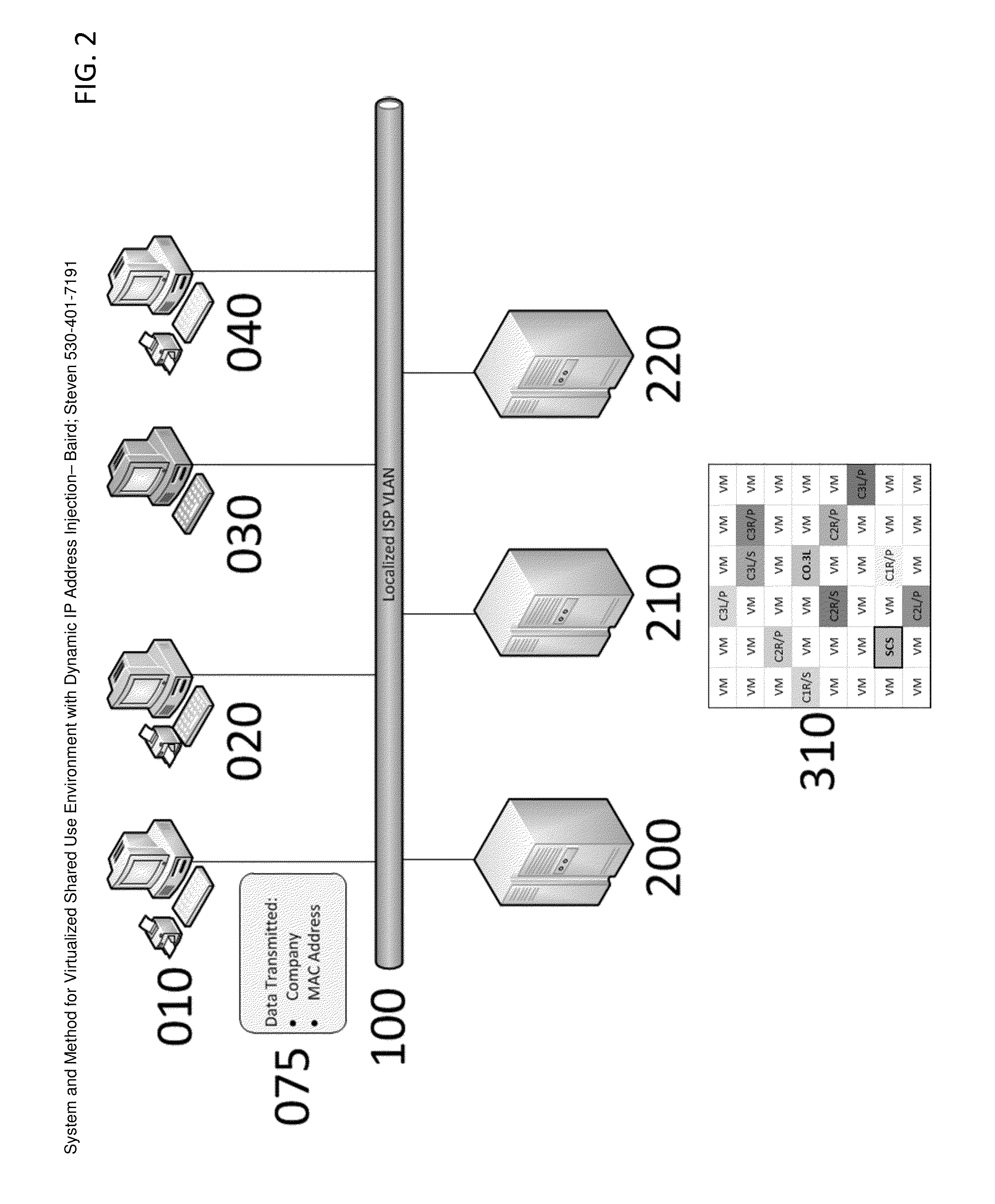
[0039]Virtual Machine Selection—In FIG. 2, the instruction set 075 is sent from edge computing device 010 through LAN 100 to the system control software running on a virtual machine 310 running on server 210. Upon receiving the instruction set, the system control software (SCS) running on a virtual machine 310 shown in FIG. 3 performs a number of operations. First the SCS queries the Equipment Location MAC Address Table 440 to determine the location type of the edge computing device 010 Using the MAC address from instruction set 075....


PUM


Abstract

Virtualized Shared Use Environment—database driven selector of specific a) company software, b) equipment location, and c) peripherals available. The selected elements together create a Virtualized Hypercart (VH) which carries all the variable elements necessary to select the appropriate running virtual machine. Derived from the above information, the system control software (SCS) selects from a table of available virtual machines that match the requirements of company software, equipment location, peripherals available and from the company software selection, the IP addressing schemes required and available for use by the virtual machine. Dynamic IP Address Injection—based on the VH, the IP addressing scheme is injected into the virtual machine that contains the appropriate company software for the type of location that made the request with the peripherals available for use by the virtual machine.

Description

BACKGROUND OF THE INVENTION[0001]1. Field of Invention[0002]The present invention is generally related to shared or common use systems where multiple types of software operate on virtual machines that are managed by system control software.[0003]2. Description of Related Art[0004]Common use systems have been available in the airport / airline industry for a number of years. It is only in recent history that the technology has caught up to enable the creation of a truly dynamic shared use environment.[0005]Common use architectures required middleware to wrap around and control the airline software. Localized hardware contained images of the middleware wrapped airline software on a partition on the hard drive. Upon a request from an operator, the partition containing the software combination would boot and become an active session. The operator was required to wait for the boot to initialize the operating system then the particular company (airline) software. All peripherals were contro...

Claims


Application Information

Patent Timeline
IPC IPC(8): G06F11/20
CPCG06F11/20G06F11/1484G06F11/2028G06F9/45558G06F2009/45595
Inventor BAIRD, STEVEN LLOYD
Owner BAIRD STEVEN LLOYD
Learn More