
Optical scanning device and image forming apparatus therewith

Inactive Publication Date: 2014-12-04
KYOCERA DOCUMENT SOLUTIONS INC
View PDF3 Cites 2 Cited by
  • Summary
  • Abstract
  • Description
  • Claims
  • Application Information

AI Technical Summary

Benefits of technology

The patent proposes a solution to correct errors in magnification caused by changes in environmental temperature in an optical scanning device. The method involves rotating a mirror to adjust the timing of detecting a light beam, which helps to distribute the error in magnification between the beginning and end of the scanning process. This ensures consistent and accurate printing even when the temperature inside the device is hot or cold.

Problems solved by technology

In such an optical scanning device, variation in the environmental temperature or the like causes variation in the refractive index of a lens, and hence variation in the characteristics of a scanning lens and the like, and this causes problems such as inconstancy in magnification (in scanning magnification) and wavy vertical lines, leading to degraded image quality.

Method used


Image

  • Optical scanning device and image forming apparatus therewith
  • Optical scanning device and image forming apparatus therewith
  • Optical scanning device and image forming apparatus therewith

Examples


first embodiment

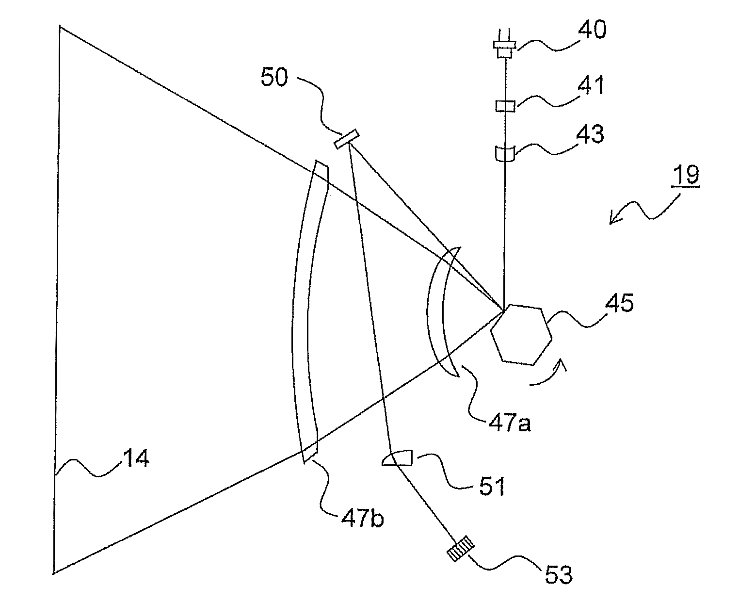
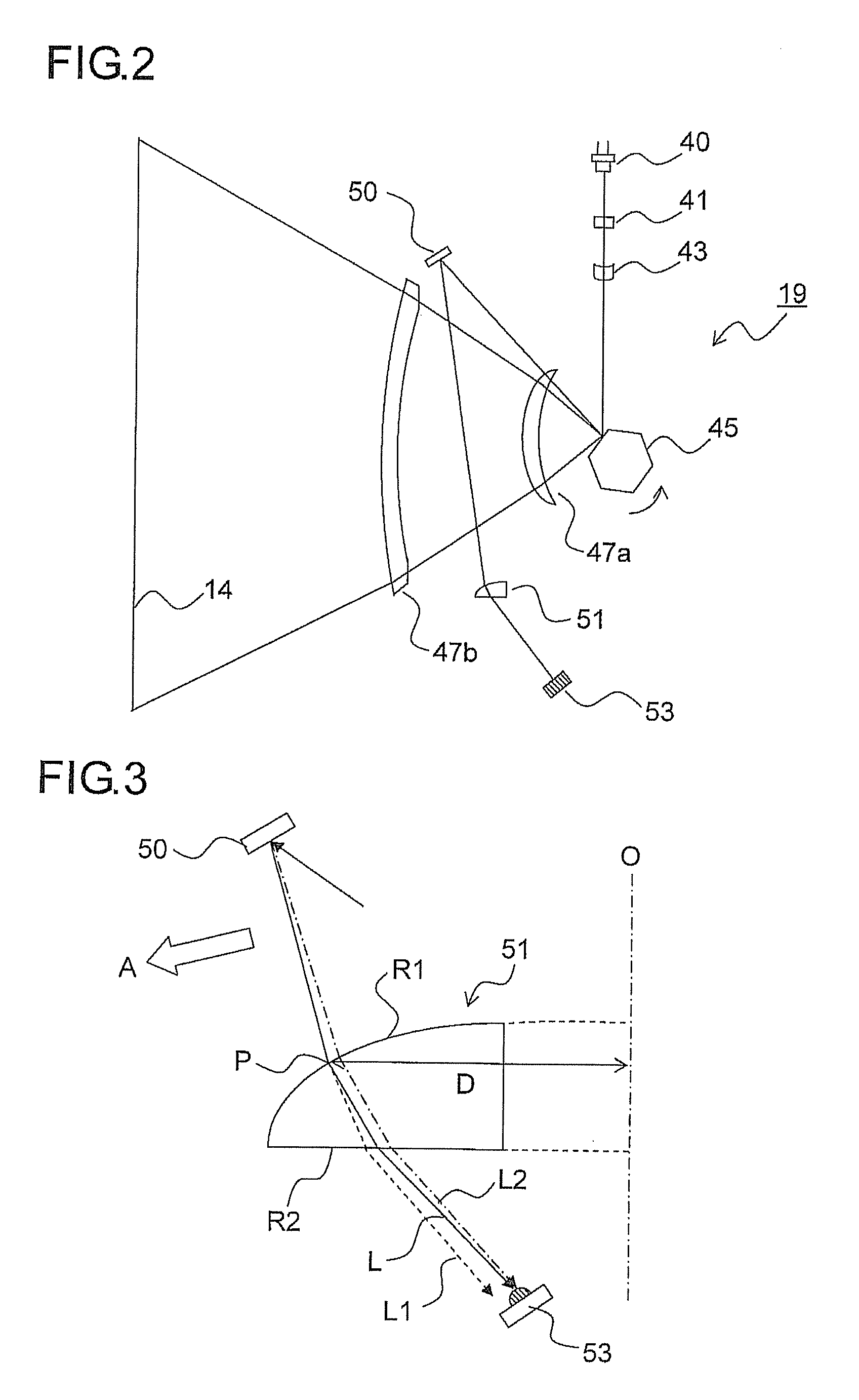
[0025]FIG. 2 is a main scanning sectional view schematically showing an internal construction of the exposure device 19 according to the present disclosure. As shown in FIG. 2, the exposure device 19 is provided with an LD unit 40, a collimator lens 41, a cylindrical lens 43, a polygon mirror 45, scanning lenses 47a and 47b, a planar mirror 50, an SOS (start-of-scan) lens 51, and a BD sensor 53.

[0026]The LD unit 40 is provided with a laser diode (LD) as a light source, and emits a light beam (laser beam) resulting from optical modulation based on an image signal. The collimator lens 41 forms the laser beam emitted from the LD unit 40 into a substantially parallel beam. The cylindrical lens 43 has a predetermined refractive power only in a sub scanning direction of the laser beam. The parallel beam having passed through the collimator lens 41 and entered the cylindrical lens 43 exits from it in the form of a convergent beam in the sub scanning direction while remaining a parallel bea...

second embodiment

[0035]FIG. 5 is a main scanning sectional view schematically showing an internal construction of the exposure device 19 in the present disclosure. FIGS. 6 and 7 are side views showing how the laser beam reflected from the planar mirror 50 passes through the SOS lens 51 and enters the BD sensor 53.

[0036]In this embodiment, as the SOS lens 51, an aspherical lens having a negative power is used. The optical axis 0 of the lens is offset, with respect to the point of entrance P, in the advancing direction (the direction indicated by arrow A in the diagrams) in the main scanning direction. The distance (optical axis offset) from the optical axis 0 of the SOS lens 51 to the point of entrance P of the laser beam L is, for example, 20 mm. The light entrance surface (surface R1) of the SOS lens 51 is, for example, an aspherical surface with a radius of curvature of 21.075 mm and a conic constant of −0.725, and the light exit surface (surface R2) of the SOS lens 51 is a flat surface. In other ...


PUM


Abstract

An optical scanning device has a light deflector deflecting a light beam from a light source, a synchronization detection sensor determining timing of starting scanning in main scanning direction based on timing of detecting the light beam scanned in main scanning direction by the light deflector, and a pre-sensor imaging optical system imaging the light beam reflected from the light deflector on the synchronization detection sensor. The pre-sensor imaging optical system moves the imaging position of the light beam on the synchronization detection sensor in a direction making the timing of detecting the light beam earlier or later according to whether variation in temperature causes the magnification of the scanning optical system in main scanning direction to increase or decrease respectively.

Description

CROSS-REFERENCE TO RELATED APPLICATIONS[0001]This application is based upon and claims the benefit of priority from the corresponding Japanese Patent Application No. 2013-113766, filed on May 30, 2013, the entire contents of which are incorporated herein by reference.BACKGROUND OF THE INVENTION[0002]The present disclosure relates to optical scanning devices for use in image forming apparatuses such as digital copiers, laser printers, and laser facsimile machines, and to image forming apparatuses provided with such optical scanning devices.[0003]In general, an optical scanning device is so configured that a light beam emitted from a beam light source device (LD unit) having a laser light-emitting portion (hereinafter “LD”) is directed through a scanning optical system composed of a collimator lens, a cylindrical lens, a deflector such as a polygon mirror, a scanning lens, etc. to be imaged as a beam spot on a scanned surface, while the deflector makes the light beam scan across the s...

Claims


Application Information

Patent Timeline
IPC IPC(8): B41J2/47
CPCB41J2/47B41J2/473G02B26/127
Inventor YOSHIDA, SHINGOSAWAMOTO, CHIKA
Owner KYOCERA DOCUMENT SOLUTIONS INC
Learn More