Reinforced flexible tubing and method of making same

a flexible tubing and reinforced technology, applied in the field of crush resistance flexible tubing, can solve the problems of corrugated rubber tubing and the degree of crush resistance that can be obtained, and achieve the effect of facilitating the sliding movement of the tube length

Inactive Publication Date: 2014-12-11
CRUSHPROOF TUBING
View PDF4 Cites 6 Cited by
  • Summary
  • Abstract
  • Description
  • Claims
  • Application Information

AI Technical Summary

Benefits of technology

[0010]The reinforcing element is formed to provide appropriate spacing between its helical convolutions to accommodate the cord used in the process. Also the reinforcing element is preferably formed of metal and, because surface portions of the reinforcing element are exposed in the interior of the tubing, stainless steel is particularly appropriate. Preferably, the internal ridges of the resulting length of tubing have a diameter slightly greater than the diameter of the mandrel so that the ridges do not engage the mandrel's cylindrical surface. This facilitates sliding movement of the tube length during its removal from the mandrel.

Problems solved by technology

A particular limitation as to corrugated rubber tubing made in accordance with the known “cording” method is the degree of crush resistance that can be obtained.
If the tubing is inadvertently crushed or collapsed for any period of time a dangerous situation could result.

Method used


Image

  • Reinforced flexible tubing and method of making same
  • Reinforced flexible tubing and method of making same
  • Reinforced flexible tubing and method of making same

Examples


Embodiment Construction

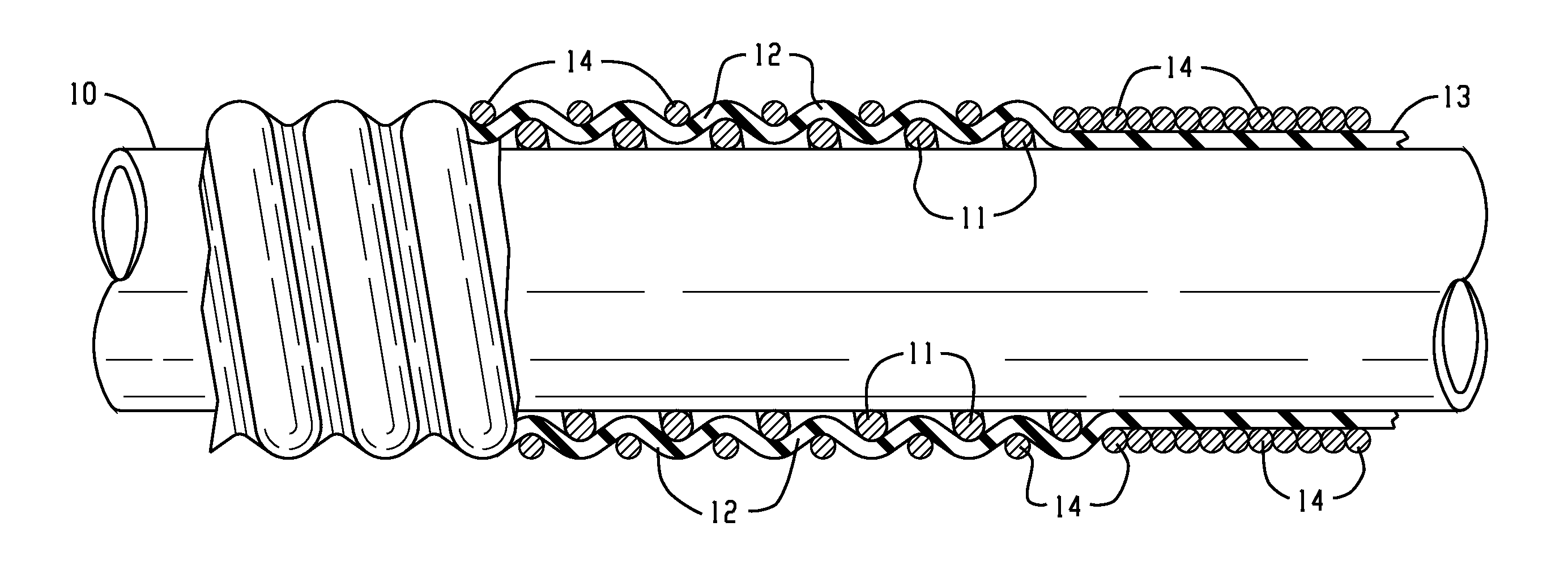
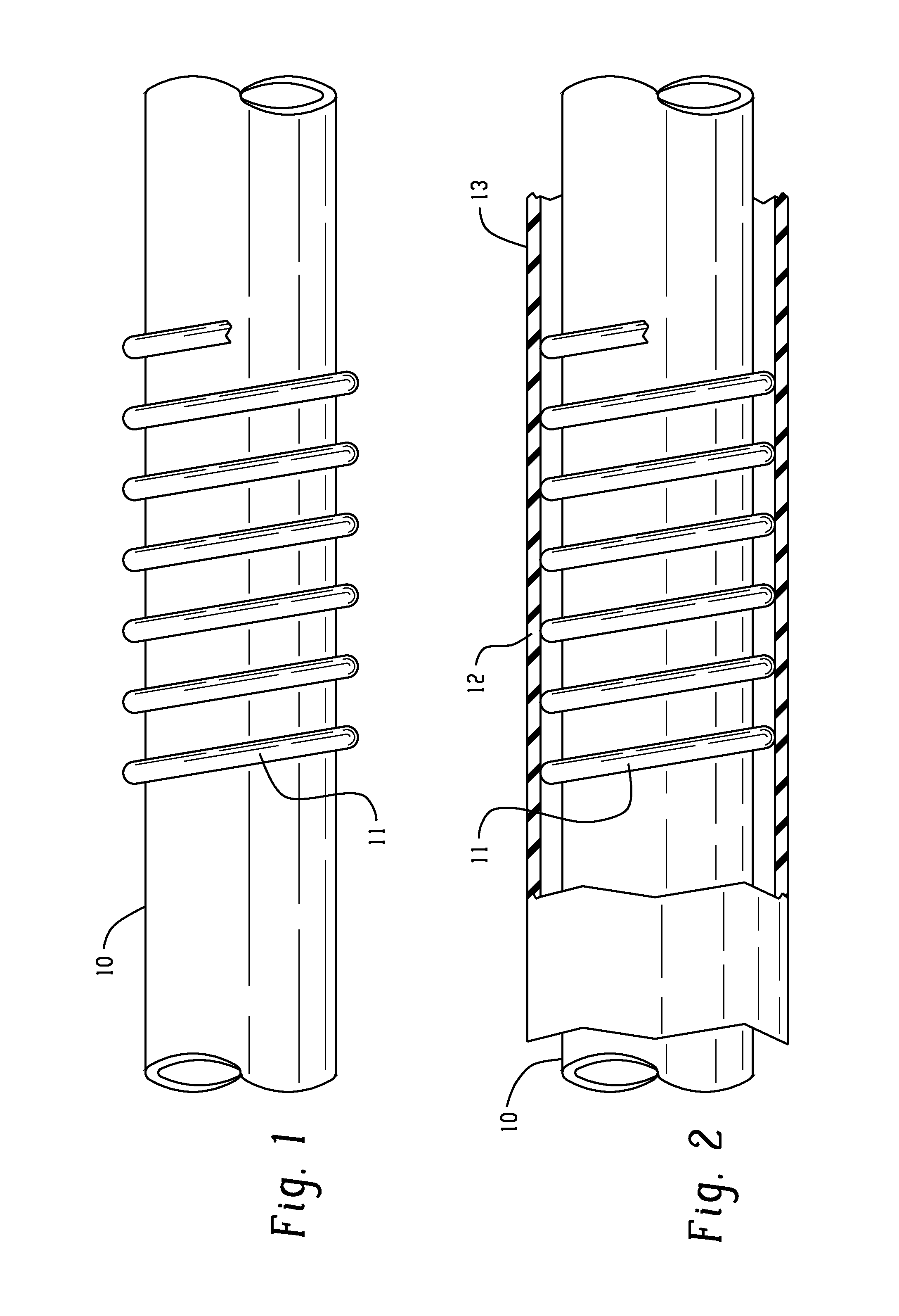
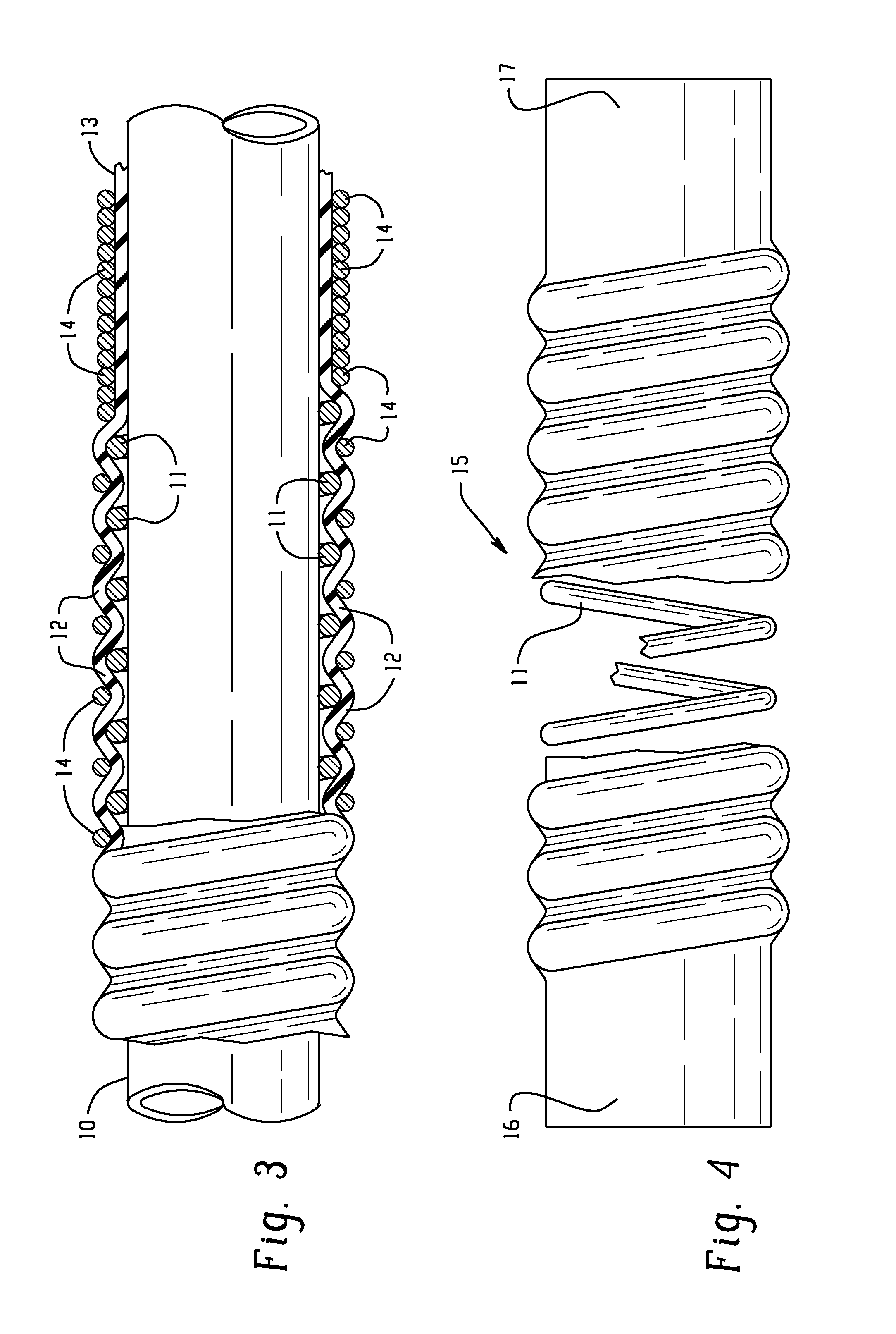
[0014]Referring more particularly to the drawings, FIGS. 1, 2 and 3 illustrate sequentially the steps used in practicing the method of the invention. The apparatus used in the process includes a cording mandrel 10 mounted on a rotatable support. In a preferred embodiment, the cording mandrel is cylindrical and is provided with a relatively smooth surface. It will be appreciated, however, that the cording mandrel could alternatively have a cross-section that defines a round shape other than that of a circle (e.g., an oval), provided that a reinforcing element 11 having a corresponding shape is used.

[0015]The process is begun by sliding a helical spring like reinforcing element 11, preferable formed of stiff metal such as stainless steel, over the cording mandrel 10 as shown in FIG. 1. It will be understood that the reinforcing element 11 may also be formed of other relatively stiff material (e.g., plastic) depending on the particular application. The convolutions of the helical reinf...


PUM

PropertyMeasurementUnit
lengthsaaaaaaaaaa
outer diameteraaaaaaaaaa
lengthaaaaaaaaaa

Abstract

A method for making helically corrugated rubber tubing with a helical reinforcing element secured therein. A helical spring like element with axially spaced convolutions is slid onto a mandrel and a sleeve formed of uncured rubber is slid over the spring like element. The mandrel is then rotated about its axis and a flexible cord is wrapped around the sleeve to press portions of the sleeve into the spaces between adjacent convolutions of the spring like element and form helical corrugations. The resulting assembly is then placed in an oven to cure the rubber sleeve after which the cord is removed. The finished product is then removed from the mandrel.

Description

BACKGROUND OF THE INVENTION[0001]1. Field of Invention[0002]This invention relates to crush resistant flexible tubing for conveying liquids and gases and, in some cases, dry granular material. The tubing is formed primarily of an elastomeric material that provides a strong but flexible length of tubing. More particularly, the invention relates to tubing that has external helical corrugations formed along its axial length as well as supplemental reinforcement secured therein. The invention also provides a method for making the reinforced tubing.[0003]2. Description of Related Art[0004]Conventionally, flexible tubing with helical corrugations to provide crush resistance has been made using a “cording” method such as is disclosed in U.S. Pat. Nos. 2,832,096; 2,879,953; 2,888,719; 2,909,198; 3,155,757 and 3,635,255; and in Pub. No. US 2013 / 0037159 A1. The aforementioned patents and published patent application are hereby incorporated by reference in their entirety.[0005]The present inve...

Claims


Application Information

Patent Timeline
Patent Type & Authority Applications(United States)
IPC IPC(8): B29C53/58F16L11/08B29C53/62
CPCB29C53/583F16L11/08B29C53/62B29C53/305F16L11/115
Inventor KRAMER, JR., VANCE M.
Owner CRUSHPROOF TUBING
Why Eureka
Try Eureka