Laser collimation and beam expansion system for deep ultraviolet lithography

A technology of laser collimation beam expansion and deep ultraviolet light, applied in the field of laser collimation beam expansion, can solve the problem that the final beam shape, size and divergence angle cannot meet the requirements of use, and achieve compact structure, small size change and convenient use. Effect

Inactive Publication Date: 2015-04-15
HUAZHONG UNIV OF SCI & TECH
View PDF10 Cites 4 Cited by
  • Summary
  • Abstract
  • Description
  • Claims
  • Application Information

AI Technical Summary

Problems solved by technology

This technology is also only applicable to the case where the outgoing laser beams have the same aperture and divergence angle in the X and Y directions. For the situation where the laser beam X and Y directions are required to have different apertures or divergence angles, this technology cannot be adjusted by adjusting the laser beam. The transmission distance makes the final beam shape and divergence angle meet the requirements of use

Method used


Image

  • Laser collimation and beam expansion system for deep ultraviolet lithography
  • Laser collimation and beam expansion system for deep ultraviolet lithography
  • Laser collimation and beam expansion system for deep ultraviolet lithography

Examples


Embodiment 1

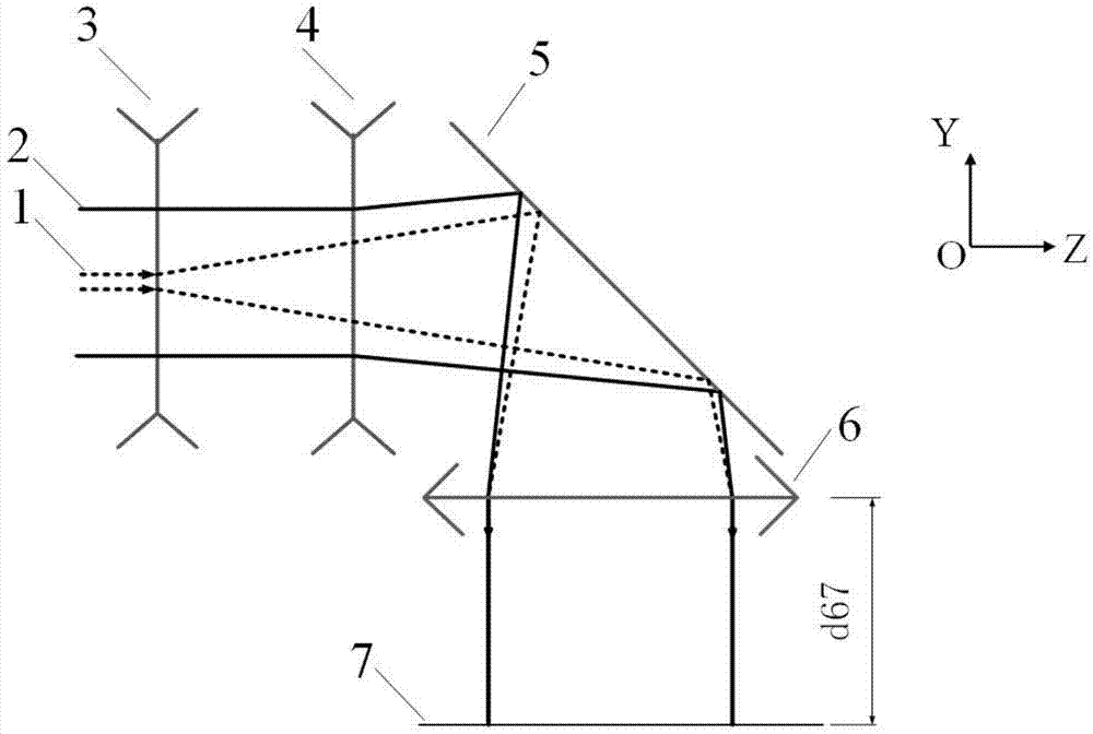
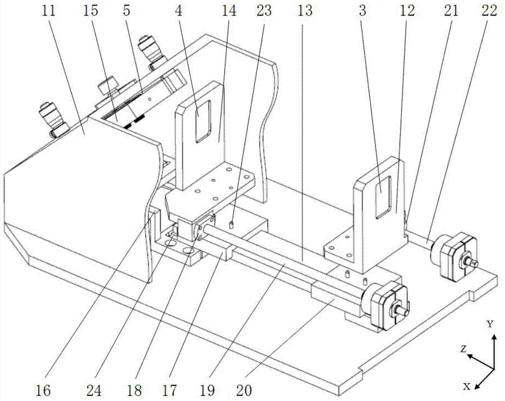
[0040] figure 1 It is a schematic diagram of the principle of the laser collimation and beam expansion system. The laser collimation and beam expansion system is composed of the first cylindrical mirror 3, the second cylindrical mirror 4, the plane mirror 5 and the spherical mirror 6. The spherical mirror 6 is connected with the first cylindrical mirror 3 respectively. and the second cylindrical mirror 4 to form two collimating beam expanders. Since the laser beam may have a divergence angle, in the present invention, the propagation direction of the center beam of the beam is taken as the propagation direction of the entire beam. Taking the propagation direction of the central beam of the laser output beam along the positive direction of the Z axis as an example, a Cartesian coordinate system is established, the focal power of the first cylindrical mirror 3 is in the X direction and is negative, and the cross-section of the laser beam emitted by the laser is at Divergence in...

Embodiment 2

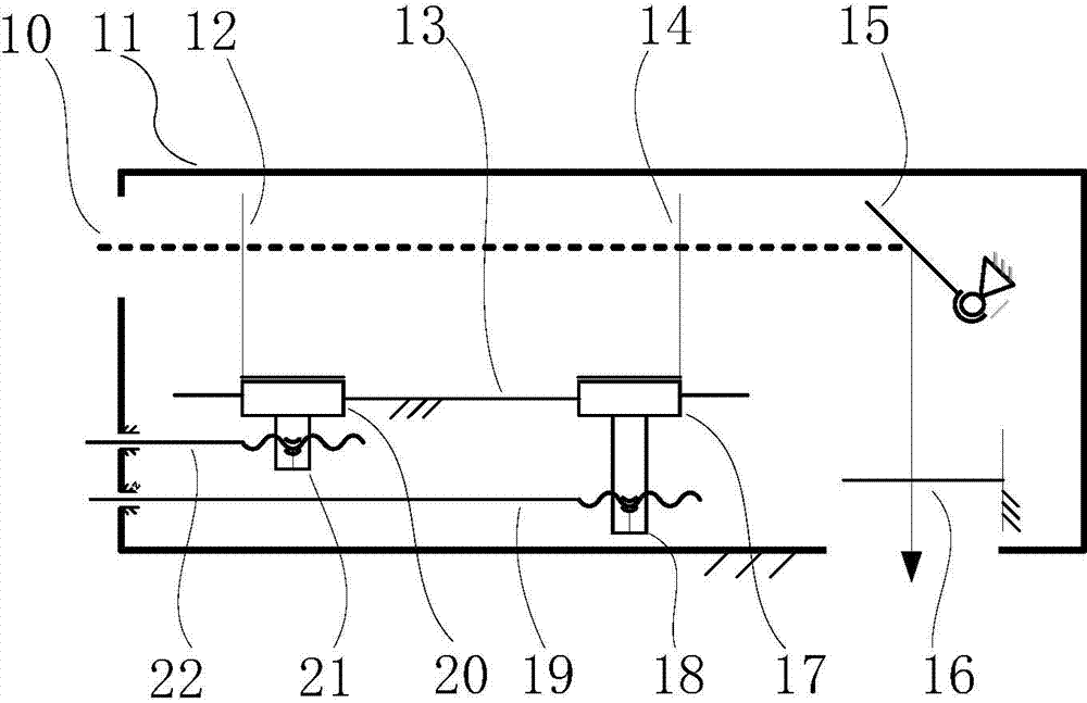
[0068] Such as Figure 4 As shown, on the basis of Embodiment 1, a second reflector 8 and a second spherical mirror 9 are added, and 7 is the light source input port in the photolithography machine. The second reflector 8 reflects the light path at 90 degrees, and its position and quantity are arranged according to needs, so that the light beam transmission path can be flexibly designed. Adding the second spherical mirror 9 can realize the beam index required in Embodiment 1 when the laser transmission distance exceeds 15m or even longer, which greatly increases the application occasions of the laser beam expander system.

[0069] Only change the beam transmission distance requirement in Embodiment 1, keep the output beam parameters of the laser light source, and require the output light source parameters to be the same as in Embodiment 1, and still use the first cylindrical mirror 3, the second cylindrical mirror 4 and the spherical mirror in Embodiment 1 6 parameters.

[0...


PUM

PropertyMeasurementUnit
wavelengthaaaaaaaaaa

Abstract

The invention discloses a laser collimation and beam expansion system for deep ultraviolet lithography. The system comprises a first cylindrical mirror, a second cylindrical mirror, a plane mirror and a spherical mirror, wherein the spherical mirror and the first and second cylindrical mirrors form two collimation beam expanders for collimating and expanding a laser beam emitted by a laser respectively; the laser beam sequentially passes through the first and second cylindrical mirrors, then is reflected by the plane mirror, is delivered to a transmission light path through the spherical mirror, and finally enters a light source input port of a lithography machine. Compared with other systems, the laser collimation and beam expansion system is more compact in structure, suitable for mounting integration, convenient to use and low in cost, can be adapted to different transmission distances, and has low requirements on distance regulation accuracy, and distance regulation can be realized by a simple regulation device.

Description

technical field [0001] The invention belongs to the field of laser collimation and beam expansion, and more specifically relates to a laser collimation and beam expansion system for deep ultraviolet lithography. Background technique [0002] The lithography machine is currently the mainstream equipment in the field of microelectronics. The lithography machine transmits the beam generated by the laser to the exposure unit, and images the pattern on the mask plate onto the silicon wafer surface of the workpiece table. The core component of this type of lithography machine is the projection exposure optical system, which is divided into two main components: the illumination system and the projection objective lens. The role of the illumination system is to provide high-uniform illumination for the entire mask surface, control the exposure dose and realize the off-axis illumination mode to improve the resolution of the lithography system and increase the depth of focus. [0003...

Claims


Application Information

Patent Timeline
Patent Type & Authority Applications(China)
IPC IPC(8): G02B27/30G02B27/09G02B1/00G03F7/20
CPCG02B27/30G02B1/00G02B27/0966G03F7/2004
Inventor 李小平陈权雷敏章伟
Owner HUAZHONG UNIV OF SCI & TECH
Why Eureka
Try Eureka