Rolling Bearing, Spindle Support Structure of Main Motor for Railway Vehicle, and Bearing Structure

a technology of rolling bearings and supporting structures, which is applied in the direction of roller bearings, mechanical energy handling, mechanical apparatus, etc., can solve the problems of inability to provide the appropriate amount of grease, the main motor cannot be enclosed, and the grease could deteriorate, so as to achieve superior sealing performance, prolong the maintenance cycle, and improve the effect of lubricating performan

Active Publication Date: 2009-12-31
NTN CORP
View PDF8 Cites 4 Cited by
  • Summary
  • Abstract
  • Description
  • Claims
  • Application Information

AI Technical Summary

Benefits of technology

[0065]According to the present invention, the rolling bearing is superior in lubricating performance and its maintenance cycle can be lengthened by specifying the bearing internal space and the projecting amount of the sealing seal having the roughly channel-shaped configuration required to enclose the appropriate amount of grease. In addition, since the sealing seal and the peripheral member form the labyrinth structure, the bearing structure is superior in sealing performance.
[0066]Furthermore, according to the present invention, since the gap δ between the inner ring and the sealing member is set within a range of 0.003≦δ≦0.015, the maintenance cycle of the rolling bearing can be lengthened.
[0067]In addition, according to the present invention, since the seal comprises the grease pocke

Problems solved by technology

In addition, since the main motor for the railway vehicle is used outdoors, in a case of an open-type bearing having a grease pocket in a bearing peripheral structure, grease could deteriorate due to entering of dust.
According to the cylindrical roller bearing provided within the above range, since the bearing internal space capacity C1 is small, the problem is that an appropriate amount of grease to ensure a bearing life required in the bearing for the railway vehicle main motor cannot be enclosed.
To increase a supplying ratio of the grease to the internal space capacity can be a way of solving the above problem, but in this case, since stirring resistance of the grease is increased while the bearing is rotated, and especially at the time of starting, so that the temperature of the bearing could be abruptly increased, which is not appropriate.
As a result, manufacturing cost of the cylindrical roller bearing 21 is increased.
In addition, the cylindrical roller bearing 31 having the above constitution has the problem that when the viscosity of the grease is lowered due to an increase in temperature at the time of rotation of the bearing, the grease in the grease pocket is concentrated at the lower part of the bearing.
However, the weirs provid

Method used


Image

  • Rolling Bearing, Spindle Support Structure of Main Motor for Railway Vehicle, and Bearing Structure
  • Rolling Bearing, Spindle Support Structure of Main Motor for Railway Vehicle, and Bearing Structure
  • Rolling Bearing, Spindle Support Structure of Main Motor for Railway Vehicle, and Bearing Structure

Examples


Embodiment Construction

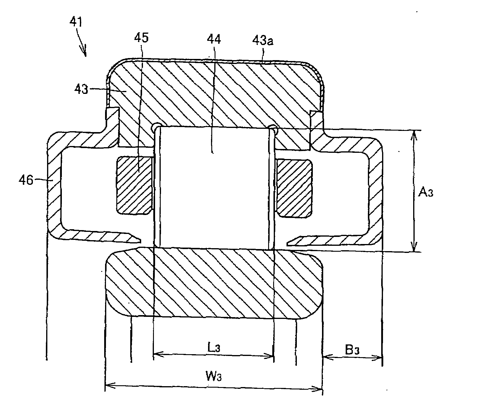
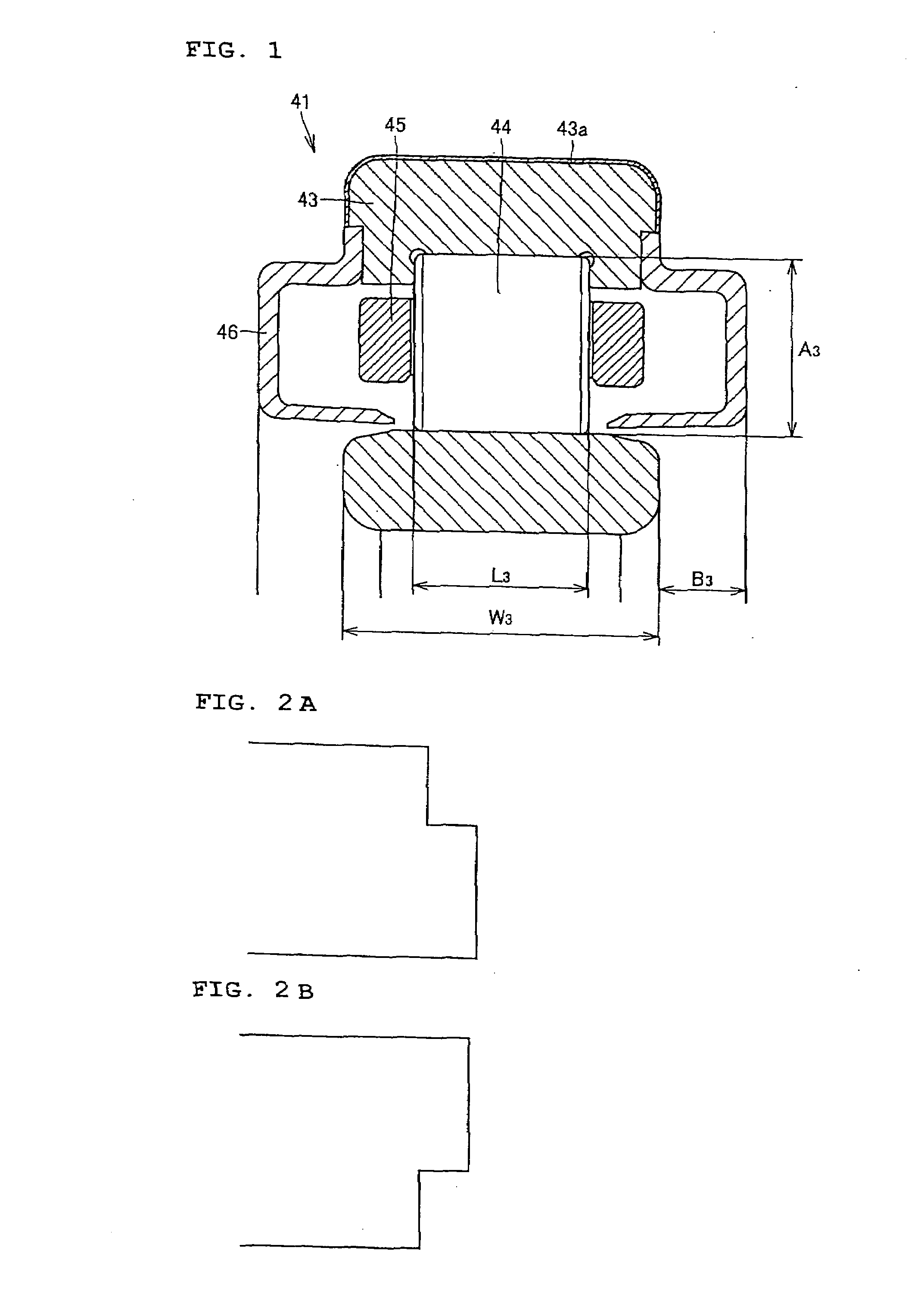
[0102]A cylindrical roller bearing 41 according to one embodiment of the present invention will be described with reference to FIG. 1.

[0103]The cylindrical roller bearing 41 comprises an inner ring 42, an outer ring 43 having the same axial width as the inner ring 42 and having an insulation layer 43a formed on an outer diameter surface and both end faces thereof, cylindrical rollers 44 as rolling bodies arranged between the inner ring 42 and the outer ring 43, a retainer 45 retaining intervals of the cylindrical rollers 44, and a sealing seal 46 as a sealing member having a roughly channel-shaped configuration in cross section projecting from both end faces of the inner ring 42 and the outer ring 43. In addition, the insulation layer 43a is formed by spraying an insulation material such as ceramics, and grease is enclosed in an internal space of the bearing.

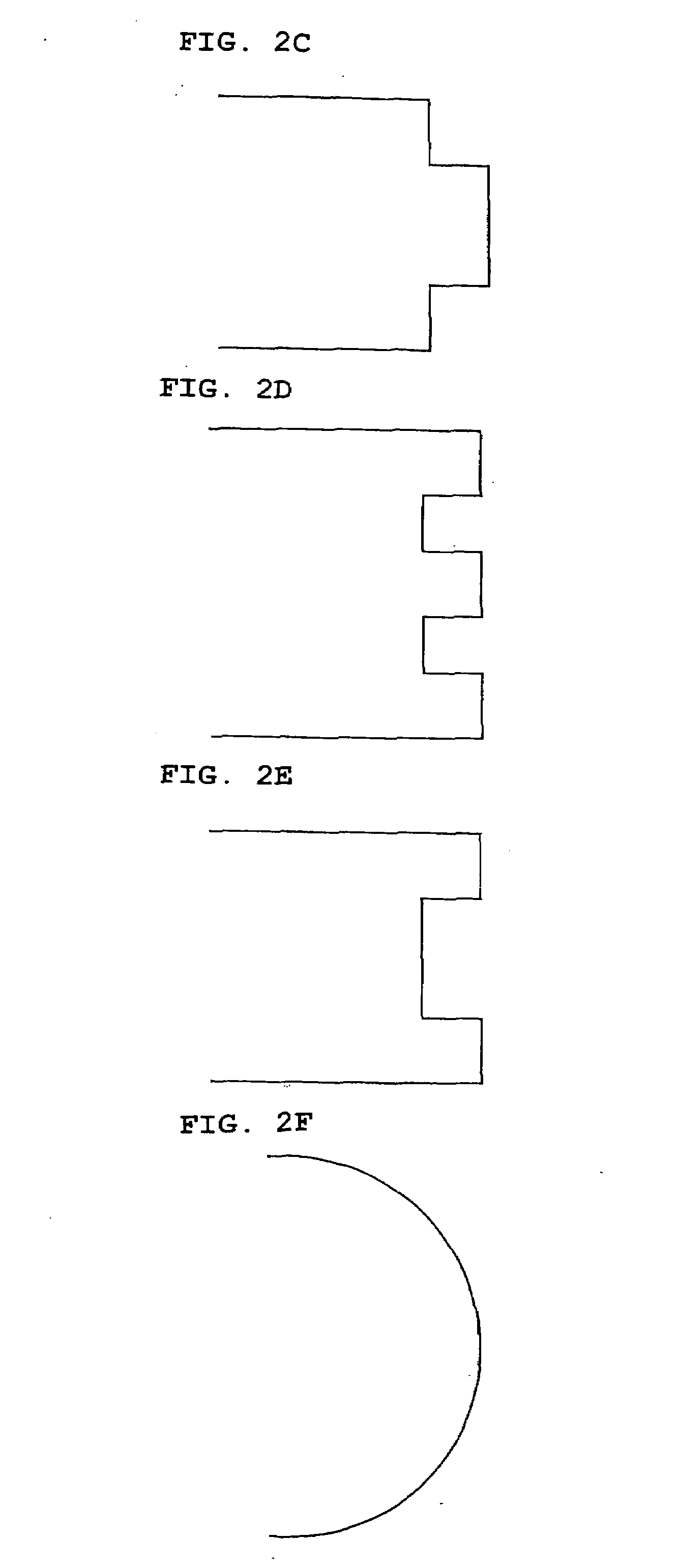
[0104]In addition, the “roughly-channel shaped configuration” in this specification is not limited to the channel shape of the...


PUM


Abstract

A cylindrical roller bearing 41 comprises an inner ring 42, an outer ring 43 having the same axial width as the inner ring 42 and having an insulation layer 43a formed on an outer diameter surface and both end faces thereof, cylindrical rollers 44 arranged between the inner ring 42 and the outer ring 43, a retainer 45 retaining intervals of the cylindrical rollers 44, and a sealing seal 46 as a sealing member having a roughly channel-shaped configuration in cross section projecting from both end faces of the inner ring 42 and the outer ring 43. Thus, a relation between a length L3 of the roller 44 and an axial width W3 of the inner ring 42 and the outer ring 43 satisfies L3/W3≧0.4, and a relation between a bearing volume V3 of the cylindrical roller bearing 41 and an internal space capacity C3 of the cylindrical roller bearing 41 satisfies 0.25≦C3/V3≦0.55.

Description

TECHNICAL FIELD[0001]The present invention relates to a rolling bearing and more particularly, to a rolling bearing required to have a long lubrication life of grease.[0002]The present invention relates to a rolling bearing and more particularly, to a spindle support structure of a main motor for a railway vehicle having an insulation layer on a track ring.BACKGROUND ART[0003]Conventionally, a cylindrical roller bearing and a deep groove ball bearing are used as a bearing used in a main motor for a railway vehicle. For example, a cylindrical roller bearing 1 shown in FIG. 17 comprises an inner ring 2, an outer ring 3, cylindrical rollers 4 as rolling bodies arranged between the inner ring 2 and the outer ring 3, and a retainer 5 retaining intervals of the cylindrical rollers 4.[0004]In addition, according to the cylindrical roller bearing 1 used in the main motor for the railway vehicle, an insulation layer 3a is formed on an outer diameter surface and both end faces of the outer ri...

Claims


Application Information

Patent Timeline
IPC IPC(8): F16C19/24F16C33/34H02K7/08
CPCF16C19/26F16C33/62F16C2202/30F16C33/7846F16C33/80F16C33/6618F16C19/06F16C33/586F16C33/782F16C2240/40F16C2380/26
Inventor SONE, KATSUNORIITO, HIDEJIYAMAKAWA, TSUKASATSUJI, NAOAKI
Owner NTN CORP
Why Eureka
Try Eureka