
Highly conductive cable with improved conductor structure and manufacturing method thereof

A conductor structure, high conductivity technology, applied in the direction of cable/conductor manufacturing, conductors, insulated cables, etc., can solve the problem of wasting copper materials, achieve the effect of increasing current carrying capacity, reducing temperature rise, and facilitating ventilation

Inactive Publication Date: 2012-02-15
刘理文 +2
View PDF10 Cites 4 Cited by
  • Summary
  • Abstract
  • Description
  • Claims
  • Application Information

AI Technical Summary

Problems solved by technology

[0008] In view of the fact that the copper material in the existing high-conductivity cable does not fully play the role of diversion, resulting in a large amount of waste of copper material, the invention provides a high-conductivity cable with an improved conductor structure and a manufacturing method thereof. The improved conductor structure of the present invention is used High-conductivity cables, which can save about 70% of copper materials by taking advantage of the carrying capacity of the cable conductors close to the critical current density

Method used


Image

  • Highly conductive cable with improved conductor structure and manufacturing method thereof
  • Highly conductive cable with improved conductor structure and manufacturing method thereof
  • Highly conductive cable with improved conductor structure and manufacturing method thereof

Examples


Embodiment 1

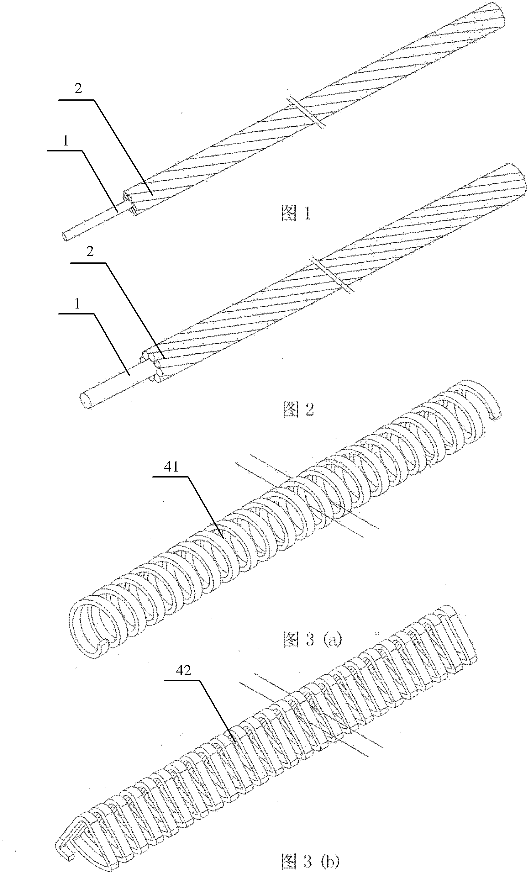
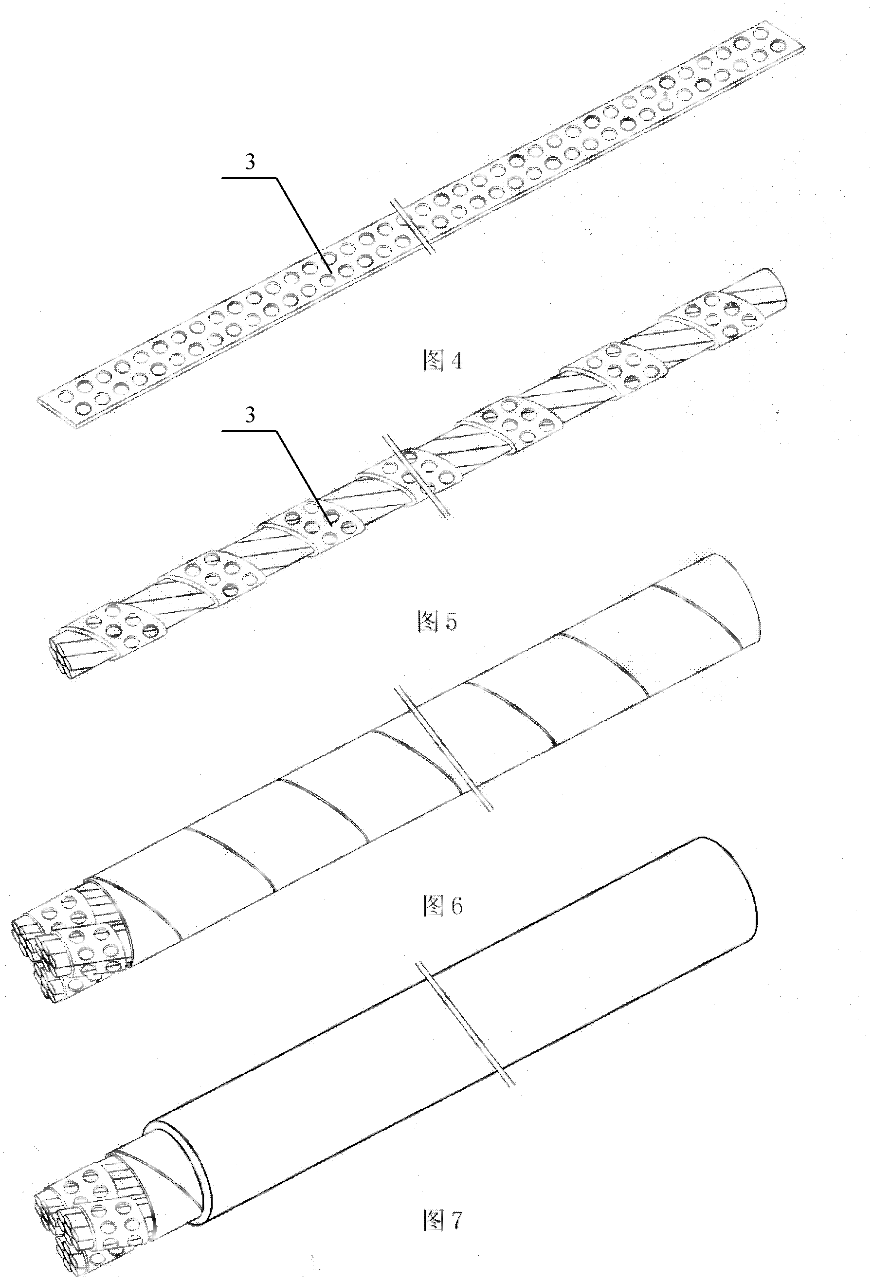
[0113] This embodiment is 3mm 2 High conductivity cable is three cores / 1.0mm 2 , by (3 / 7 / 0.427mm) bare copper wire conductor 2 is twisted on the periphery of non-concentric tensile PE plastic core wire 1 to make a stranded conductor 6, wherein "non-concentric circle" refers to the tensile PE plastic core wire 1 The diameter of the stranded conductor 6 is not equal to the diameter of the bare copper wire conductor 2, and the outer edge of the stranded conductor 6 is wrapped with a PE / PVC insulating tape 3 with holes, the 3mm of the present embodiment 2 The high-conductivity cable is made of three-strand conductors 6 twisted and covered with PE Mylar and extruded. The steps of its specific manufacturing method are as follows:

[0114] (1) Use 7 sticks 0.427mm conductor 2 is wrapped around the same core round tensile PE plastic core wire 1, twisted into 1.0mm 2 Stranded conductors of 6 ( figure 2 )spare;

[0115] (2) Take a flat PE / PVC insulating tape with holes ( Fi...

Embodiment 2

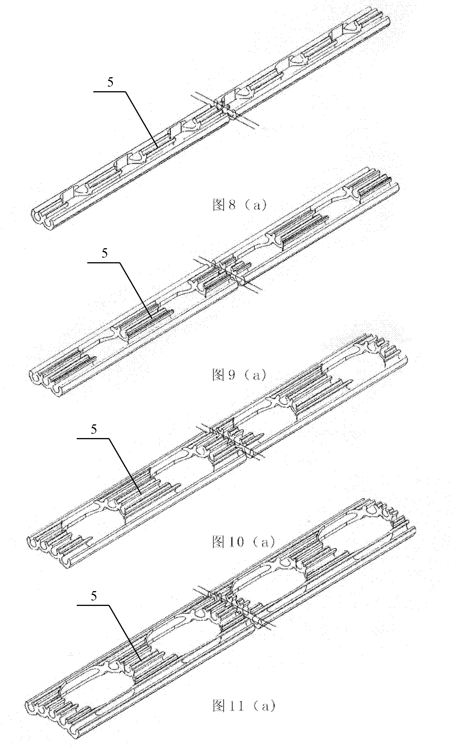
[0120] This embodiment is a single core 40mm 2 High conductivity cable is 35 cores / 1.145mm 2 , by (35 / 8 / 0.427mm) bare copper wire conductor 2 is twisted on the periphery of non-concentric tensile PE plastic core wire 1 to make a stranded conductor 6, wherein "non-concentric circle" refers to the tensile PE plastic core wire 1 The diameter is not equal to the diameter of the bare copper wire conductor 2. The conductor holder 5 of the present embodiment is flat, including two types of two grooves and three grooves, and the first layer around the circumference of the circular hollow spiral body 41 is seven strands of two grooves embedded with twisted conductors 6 Conductor holder 5, the second layer is a three-groove conductor holder 5 embedded with stranded conductors 6, the 40mm of the present embodiment 2 The high-conductivity cable is made by adding PE Mylar to the above-mentioned two-layer conductor, extruding and covering, and the stranded conductor 6 with the insulati...

Embodiment 3

[0139] In this embodiment, the three cores are 16mm 2 High conductivity cable is 14 / 1.145mm 2 , by (14 / 8 / 0.427mm) bare copper wire conductor 2 is twisted on the periphery of non-concentric tensile PE plastic core wire 1 to make a stranded conductor 6, wherein "non-concentric circle" refers to the tensile PE plastic core wire 1 The diameter is not equal to the diameter of the bare copper wire conductor 2. The conductor fixing frame 5 of the present embodiment is flat, and comprises four types of conductor fixing frames 5 of two grooves, three grooves, four grooves and five grooves. The two grooves, three grooves, four grooves and five grooves of the conductor 6 are overlapped to form the conductor fixing frame 5, and the three cores of the present embodiment are 16mm 2The high-conductivity cable is composed of a single core wire of the above-mentioned three-axis high-conductivity cable and three special-shaped hollow helixes 42 that are evenly spaced around each other and ...


PUM

PropertyMeasurementUnit
diameteraaaaaaaaaa
areaaaaaaaaaaa
areaaaaaaaaaaa

Abstract

The invention discloses a highly conductive cable with an improved conductor structure and a manufacturing method thereof, which belongs to the field of cables. In the highly conductive cable with the improved conductor structure, a plurality of conductors are stranded at the periphery of a concentric circle or non-concentric circle core wire to be manufactured into stranded conductors; the stranded conductors are embedded into grooves of hollow, circular and porous multi-groove conductor mounting brackets, or, flat conductor mounting brackets embedded with the stranded conductors are encircled at the periphery of a hollow and circular screw, and then are packed by polyurethane (PE) tapes or PE wire mylar, or, a plurality of flat conductor mounting brackets embedded with the stranded conductors are overlapped into multi-core highly conductive cable core wires; the outer edges of the multi-core highly conductive cable core wires are packed by a porous insulating tape; and the multi-core highly conductive cable core wires and a hollow special-shape screw are evenly encircled at the periphery of the hollow and circular screw at intervals. By adopting the highly conductive cable with the improved conductor structure, the area of each conductor is minimized; the skin effect is maximized; the current-carrying capacity of the area of the conductor is increased; a copper material is saved by about 70 percent; and simultaneously, the porous conductor mounting brackets are adopted, thereby, the highly conductive cable with the improved conductor structure is beneficial to ventilation, reduces temperature rise and has an effect of increasing the current-carrying capacity.

Description

technical field [0001] The invention relates to the field of cables, more specifically, to a high-conductivity cable with an improved conductor structure and a manufacturing method thereof. The improved conductor structure can save nearly 70% of copper material. Background technique [0002] Today's climate change is unpredictable, sometimes there are flash floods, storms, tsunamis, and earthquakes, and Changming's technology is also difficult to cope with. Superconducting cables have entered the experimental period, which is a great boon for energy conservation. Due to the cumbersome production process and high cost, it will take at least 20 to 30 years to replace underground high-voltage cables. The ampacity of high conductivity cables is 1 to 2 times that of traditional cables, but it is still not ideal. [0003] Existing wires and cables except for a single conductor, most of the wires and cables composed of multiple conductors have to be twisted once or more times. As ...

Claims


Application Information

Patent Timeline
Patent Type & Authority Applications(China)
IPC IPC(8): H01B7/00H01B7/02H01B7/17H01B7/42H01B5/08H01B5/10H01B13/00
Inventor 刘理文刘维廉刘维人
Owner 刘理文
Learn More