Elements for Joining Two Workpiece Parts by Means of Laser Beam Welding

a technology of laser beam welding and components, which is applied in the direction of laser beam welding equipment, welding equipment, manufacturing tools, etc., can solve the problems of high production cost, adverse affecting welding, and stress on the workpiece, and achieve cost-effective production.

Inactive Publication Date: 2014-12-11
JENOPTIK AUTOMATISIERUNGSTECHN
View PDF43 Cites 5 Cited by
  • Summary
  • Abstract
  • Description
  • Claims
  • Application Information

AI Technical Summary

Benefits of technology

[0017]An object of the present invention is to provide a device for joining two workpiece parts by laser beam welding with an, as simple as possible, and cost-effectively producible, pressure unit, with which the workpiece parts may be flat welded with compensation of workpiece tolerances for a variety of weld seams.

Problems solved by technology

However, the pressure applied to one side of the weld seam may adversely affect the welding result.
Because the workpiece parts are heated during the welding, they may be deformed by the pressure force acting on one side, which can result in stresses in the workpiece after cooling, which in turn can lead to deformations.
For larger and more complex shaped workpiece parts, this quickly results in very high production costs.
A disadvantage of the design of the homogenizer, which can also be understood to mean a pressure unit, is the required specific design of the carrier to match the course of the weld seams and its fixed arrangement in the direction of the pressure force.

Method used


Image

  • Elements for Joining Two Workpiece Parts by Means of Laser Beam Welding
  • Elements for Joining Two Workpiece Parts by Means of Laser Beam Welding
  • Elements for Joining Two Workpiece Parts by Means of Laser Beam Welding

Examples


Embodiment Construction

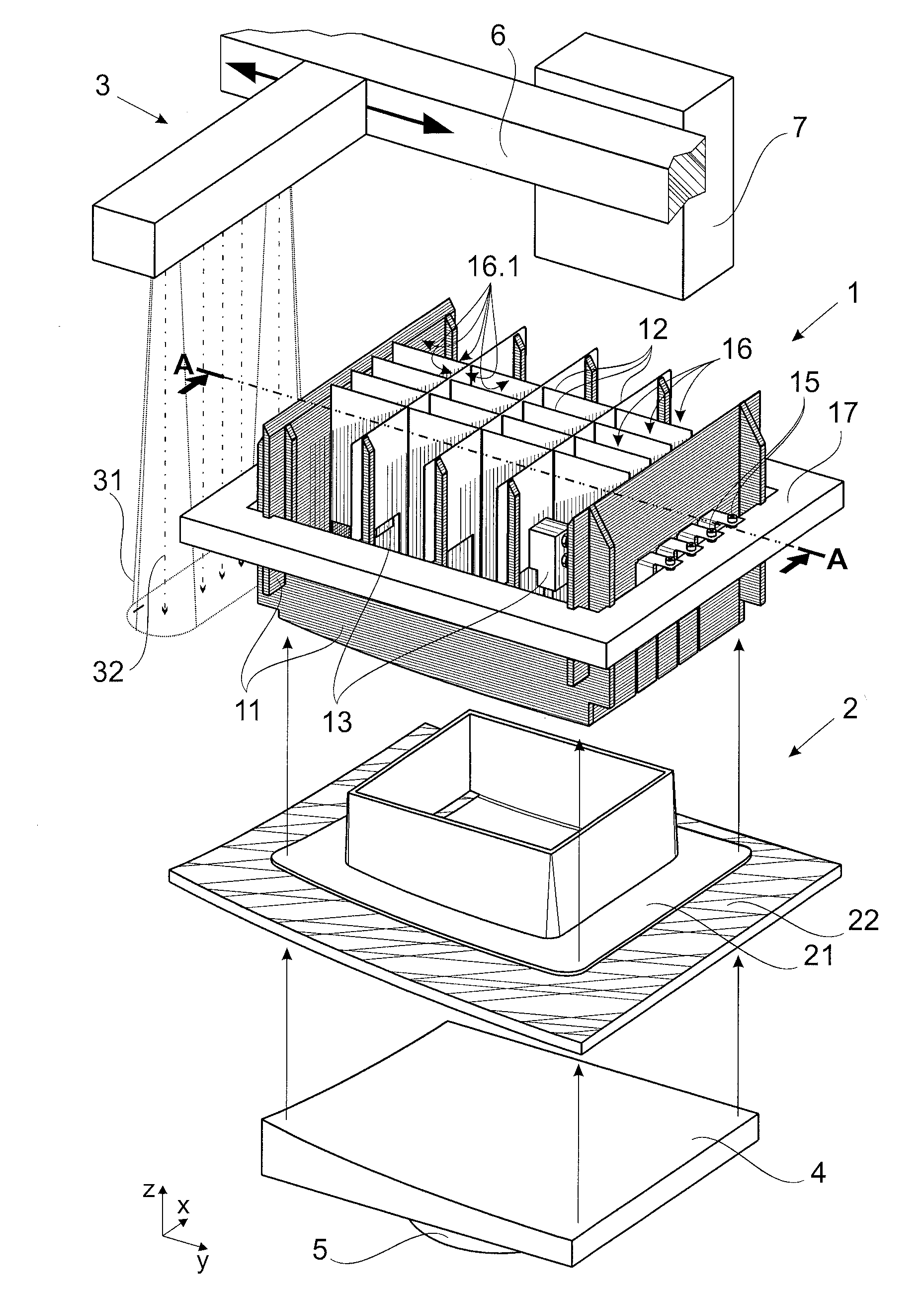
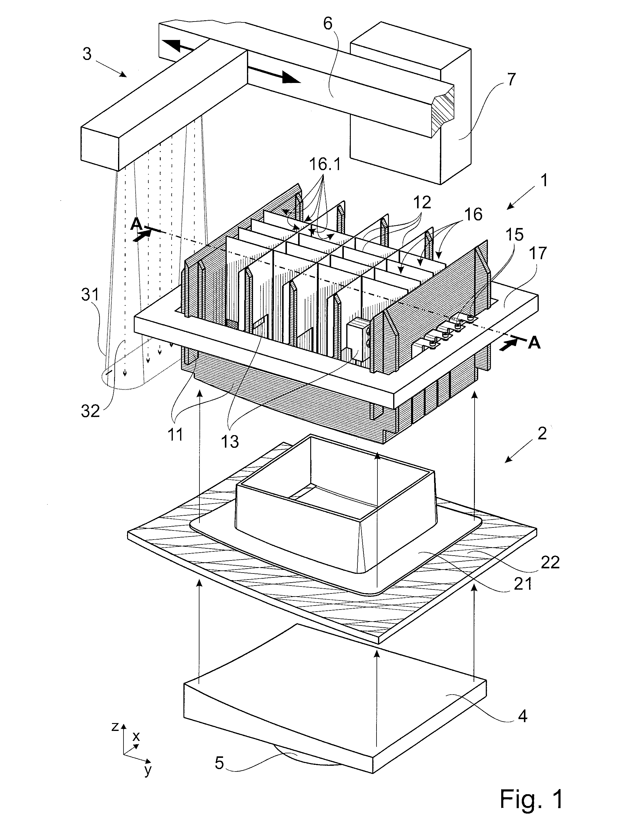
[0041]According to a first embodiment illustrated in FIG. 1, the device for laser beam welding has a holder 4 with a pressure cylinder 5, a pressure unit 1, a movement device 6 with a laser beam source 3 and a memory and control unit 7.

[0042]An absorbent workpiece part 22 and a translucent workpiece part 21 are inserted into the holder 4 and are welded to form workpiece 2. The absorbent workpiece part 22 is absorbent for the laser beam 31 emitted by the source 3, while the translucent workpiece part 21 is transmissive for the laser beam 31. First the absorbent workpiece 22 and then the translucent workpiece part 21 are inserted in the holder 4, so that the latter faces the laser beam source 3.

[0043]By insertion into the holder 4, the workpiece 2 is positioned in the x, y and z directions of a Cartesian coordinate system.

[0044]The laser beam source 3 is arranged in the z direction opposite the holder 4. The laser beam 31 emitted by the laser beam source 3 is preferably perpendicular ...


PUM

PropertyMeasurementUnit
thicknessaaaaaaaaaa
pressureaaaaaaaaaa
pressure forceaaaaaaaaaa

Abstract

A device for connecting two workpiece parts by means of laser beam welding. Producing a simply constructed and cost-effectively manufactured device for flat welding workpiece parts, with simultaneous compensation of workpiece tolerances, is achieved by a weld seam pattern with a number of weld seams arranged downstream of an adapted pressure unit of a laser beam source. The pressure unit has a plurality of channels extending through it with channel walls. The channel walls are a lattice-like arrangement of the first and second pressure elements which have integrated means for compensating tolerances, and which are designed to press the workpiece parts against one another in the z direction.

Description

RELATED APPLICATIONS[0001]The present application claims priority benefit of German Application No. DE 10 2013 105 881.7 filed on Jun. 6, 2013, the contents of which is incorporated by reference in its entirety.FIELD OF THE INVENTION[0002]The invention relates to a device for connecting two workpiece parts by means of laser beam welding, as is known generically from DE 10 2011 055 203 A1.BACKGROUND OF THE INVENTION[0003]In laser beam welding, there is a first workpiece part for the laser beam transmission and a second workpiece part for the laser beam absorption. The two workpiece parts are placed one above the other, whereby the transmitting workpiece part faces the laser beam source. The laser beam penetrates the first workpiece part, impinges on the surfaces of the second workpiece part, is absorbed in an area bordering the surfaces, and is converted into heat energy. The surface in the area of the second workpiece part impinged by the laser beam melts, whereby the adjacent porti...

Claims


Application Information

Patent Timeline
Patent Type & Authority Applications(United States)
IPC IPC(8): B23K26/24
CPCB23K26/24B29C65/1635B29C65/1658B29C65/1664B29C65/1674B29C65/1687B29C65/1696B23K26/10B23K26/28B29C66/112B29C66/131B29C66/301B29C66/3452B29C66/532B29C66/61B29C66/81422B29C66/81423B29C66/81453B29C66/81461B29C66/8322B29K2995/0027B29C66/73365B23K26/037
Inventor STEINER, CHRISTOPHWOLLMANN, WERNER
Owner JENOPTIK AUTOMATISIERUNGSTECHN
Why Eureka
Try Eureka