
Propulsion system in two modules for satellite orbit control and attitude control

a propulsion system and satellite technology, applied in the field of satellite orbit control and attitude control systems, can solve the problems of high initial weight and the effectiveness of thrusters, or their capacity to generate, and achieve the disadvantage of different thrusters and fuel, high cost and high weigh

Active Publication Date: 2014-12-11
THALES SA
View PDF5 Cites 45 Cited by
  • Summary
  • Abstract
  • Description
  • Claims
  • Application Information

AI Technical Summary

Benefits of technology

The patent is about a device that reduces the amount of force generated by a satellite's motion. This force can cause the satellite to become unbalanced, which can be a safety risk. The device uses two thrusters to create a force in the opposite direction, which helps to stabilize the satellite and reduce the force absorbed by it.

Problems solved by technology

Although costly and of great initial weight, the effectiveness of the thruster, or its capacity to generate force by mass ejection, also called specific impulsion, is substantially greater than that of chemical thrusters.
The propulsion systems that are thus implemented have the drawback of a high cost and high weight, different thrusters and fuel.
These drawbacks limit the payload capacity of the satellite.
Thus, the cost and the weight of the current propulsion systems limit the capacity to have a high payload onboard.
Techniques have also been developed to allow for eccentricity corrections on a second axis, by offsetting the firing of the thruster relative to the orbital node, but at the cost of less effective control of the inclination.
The current solutions, which implement thrusters of different kinds of different locations on the satellite are relatively complex, costly and exhibit a high weight which limits the onboard capacity of the satellite.

Method used


Image

  • Propulsion system in two modules for satellite orbit control and attitude control
  • Propulsion system in two modules for satellite orbit control and attitude control
  • Propulsion system in two modules for satellite orbit control and attitude control

Examples


first embodiment

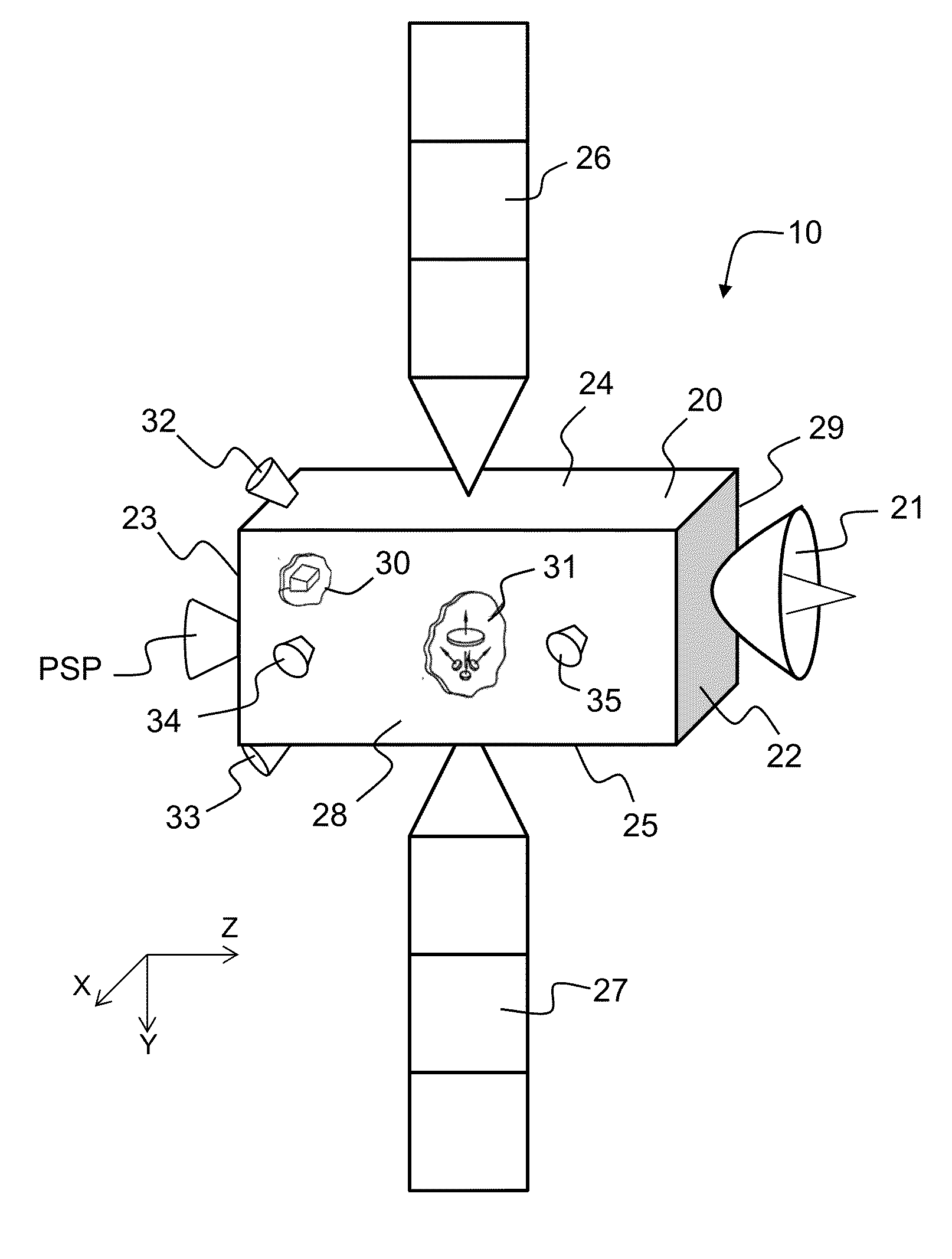
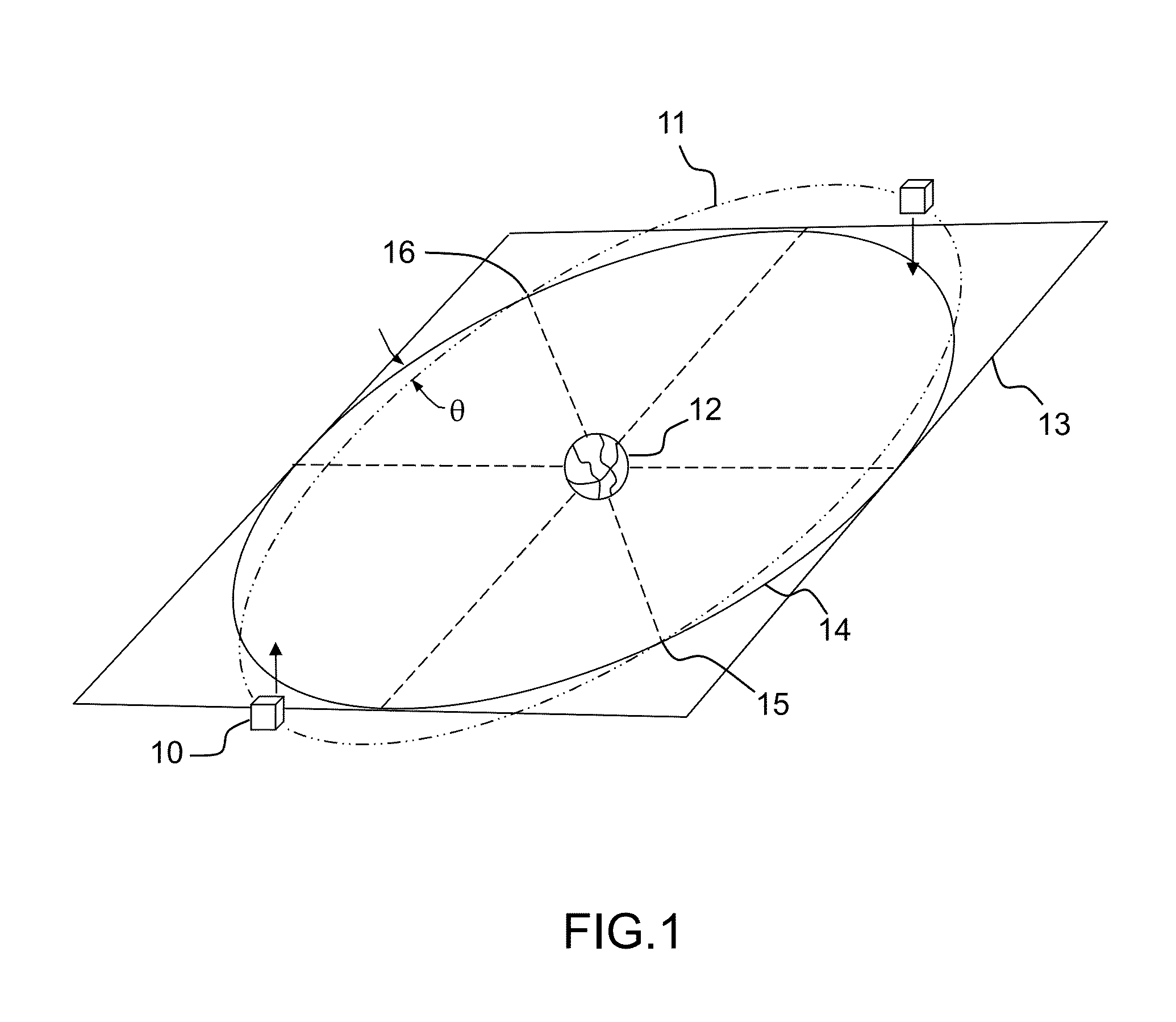
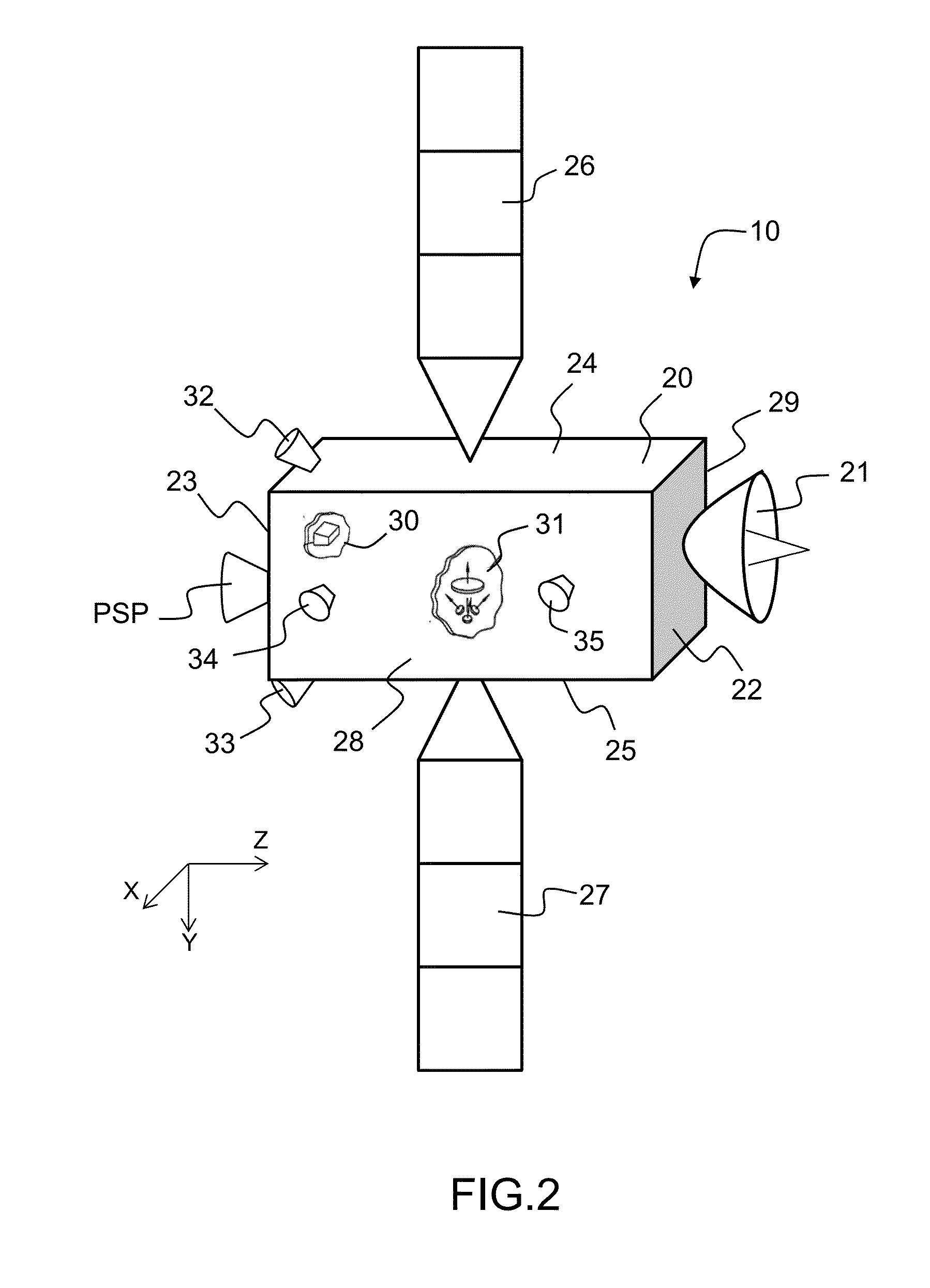
[0062]FIGS. 4a, 4b and 4c represent the propulsion system respectively in storage position, in orbit transfer position and in operational position. As previously described, a satellite 10 in orbit 11 is stabilized on three axes of a reference trihedron linked to the satellite by means of an attitude control system. The reference trihedron comprises an axis Z oriented towards the Earth, an axis Y at right angles to the orbit and oriented in the direction opposite to the kinetic moment of the orbital rotation, and an axis X forming, with the axes Y and Z, a direct orthogonal reference frame. The axis X is oriented in the direction of the speed of the satellite in orbit 11 around the Earth 12. The satellite 10 comprises a parallelepipedal structure 20 with two faces 22 and 23, called Earth face and anti-Earth face, that are at right angles to the axis Z and oriented respectively towards the Earth and towards a direction opposite the Earth, and two opposite adjacent faces 24 and 25, cal...

second embodiment

[0080]In this second embodiment, each of the two thrusters, respectively 54a and 55a, comprises a redundant thruster, respectively 66a and 67a, arranged on the plate in proximity to said main thruster, respectively 54a and 55a, and in such a way that its thrust axis is contained in a plane containing the thrust axes of the two main thrusters 54a and 55a.

[0081]Provision is made for the possibility of not having them arranged strictly parallel so as to best accommodate the interactions of the jet of the thrusters with the other components of the satellite—notably its appendages—or any other constraint of configuration or of optimization of the management of the kinetic moment via the torques generated.

[0082]In the case of a satellite with circular orbit referenced by means of the reference trihedron (X, Y, Z) represented in the figures, this means that the thrust axes of the four thrusters (two main thrusters and two redundant thrusters) are parallel to one another and at right angle...

third embodiment

[0085]Thus, the propulsion system according to this third embodiment comprises, for each of the two propulsion modules, between the offset arm 52a and the plate 53a of said module 50a, a second motorized rotation link 70a about an axis T at right angles to both the axis V and the thrust axes of the two thrusters 54a and 55a of said propulsion module 50a.

[0086]FIG. 6a represents the propulsion module in operational position. The plane containing the thrust axes of the thrusters passes through the centre of mass CM of the satellite. The second motorized link 70a is in a centered position; the thrust axes of the thrusters being aligned on the axis Z. This is also the position of the propulsion module represented in FIG. 6b. In this view, the propulsion module is presented in the plane containing the thrust axes of the thrusters. This plane is at right angles to the axis T of rotation of the second motorized link 70a, it contains the axis R1a of the first motorized link 51a. In this ce...


PUM


Abstract

A propulsion system for the orbit control of a satellite in Earth orbit driven at a rate of displacement along an axis V tangential to the orbit comprises two propulsion modules, fixed to the satellite, and facing one another relative to the plane of the orbit, each of the propulsion modules comprising, in succession: a motorized rotation link about an axis parallel to the axis V; an offset arm; and a plate supporting two thrusters, suitable for delivering a thrust on an axis, arranged on the plate on either side of a plane P at right angles to the axis V passing through a centre of mass of the satellite; each of the two thrusters being oriented in such a way that the thrust axes of the two thrusters are parallel to one another and at right angles to the axis V.

Description

CROSS-REFERENCE TO RELATED APPLICATION[0001]This application claims priority to foreign French patent application No. FR 1301302, filed on Jun. 7, 2013, the disclosure of which is incorporated by reference in its entirety.FIELD OF THE INVENTION[0002]The present invention relates to the field of satellite orbit control and attitude control systems, and more particularly, to the architecture of the onboard propulsion systems for controlling the orbit of geostationary telecommunications satellites.BACKGROUND[0003]In order to allow for the use of the various mission instruments of a satellite, such as telecommunication systems, it should be possible to control the position and the orientation of the satellite in orbit. For this, control systems are implemented for maintaining, on the one hand, the orientation of the satellite relative to the Earth, that is to say the attitude control, and, on the other hand, its position in orbit relative to a desired ideal position, that is to say orbi...

Claims


Application Information

Patent Timeline
Patent Type & Authority Applications(United States)
IPC IPC(8): B64G1/24B64G1/26
CPCB64G1/26B64G1/242B64G1/1007B64G1/283B64G1/2429B64G1/2427B64G1/262B64G1/413B64G1/405B64G1/40
Inventor CELERIER, BRUNO
Owner THALES SA
Learn More