
Cam lock fence system and method of use

Active Publication Date: 2014-12-11
KREG ENTERPRISES
View PDF29 Cites 17 Cited by
  • Summary
  • Abstract
  • Description
  • Claims
  • Application Information

AI Technical Summary

Benefits of technology

This patent is for a cam lock that is connected to a fence assembly and can be easily unlocked or locked using a handle. The lock consists of upper and lower carriers that are connected by a threaded shaft. The upper carrier is positioned above the fence assembly and a work table, while the lower carrier is positioned below the fence assembly and work table. The upper and lower carriers have alignment arms that fit together, and the handle has cam surfaces that engage with the alignment arms of the top carrier. This allows for quick, durable, and accurate locking or unlocking of the fence assembly by rotating the handle. Overall, this cam lock makes it simple to lock and unlock the fence assembly.

Problems solved by technology

While these stop and alignment systems are functional, many of them suffer from substantial disadvantages.
Namely, many conventional stop and alignment systems are expensive to produce or are formed of many pieces.
Other stop and alignment systems are complex and difficult for the user to set and adjust, or are extremely time consuming to set up.
Yet other stop and alignment systems fail to provide an accurate, repeatable and durable way of aligning the workpiece for an operation.

Method used


Image

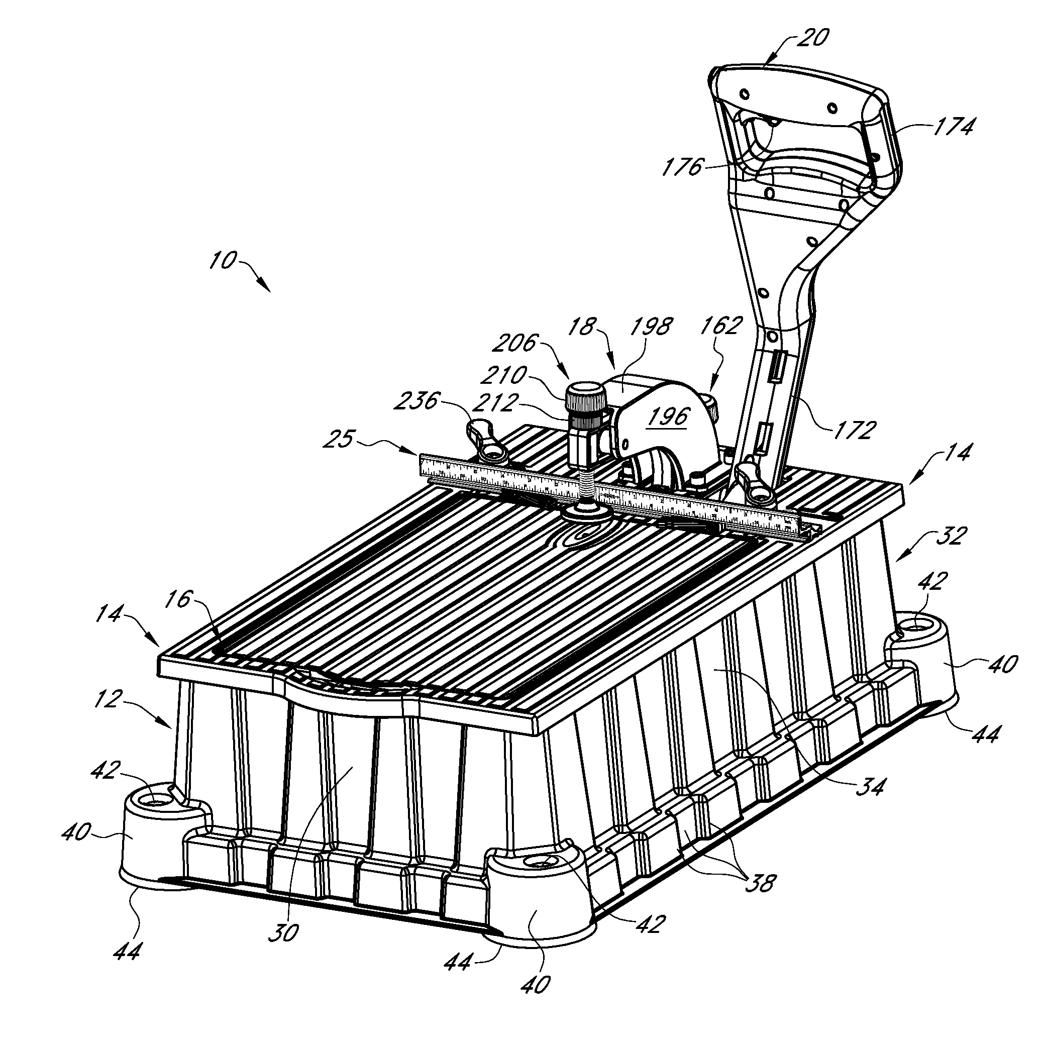
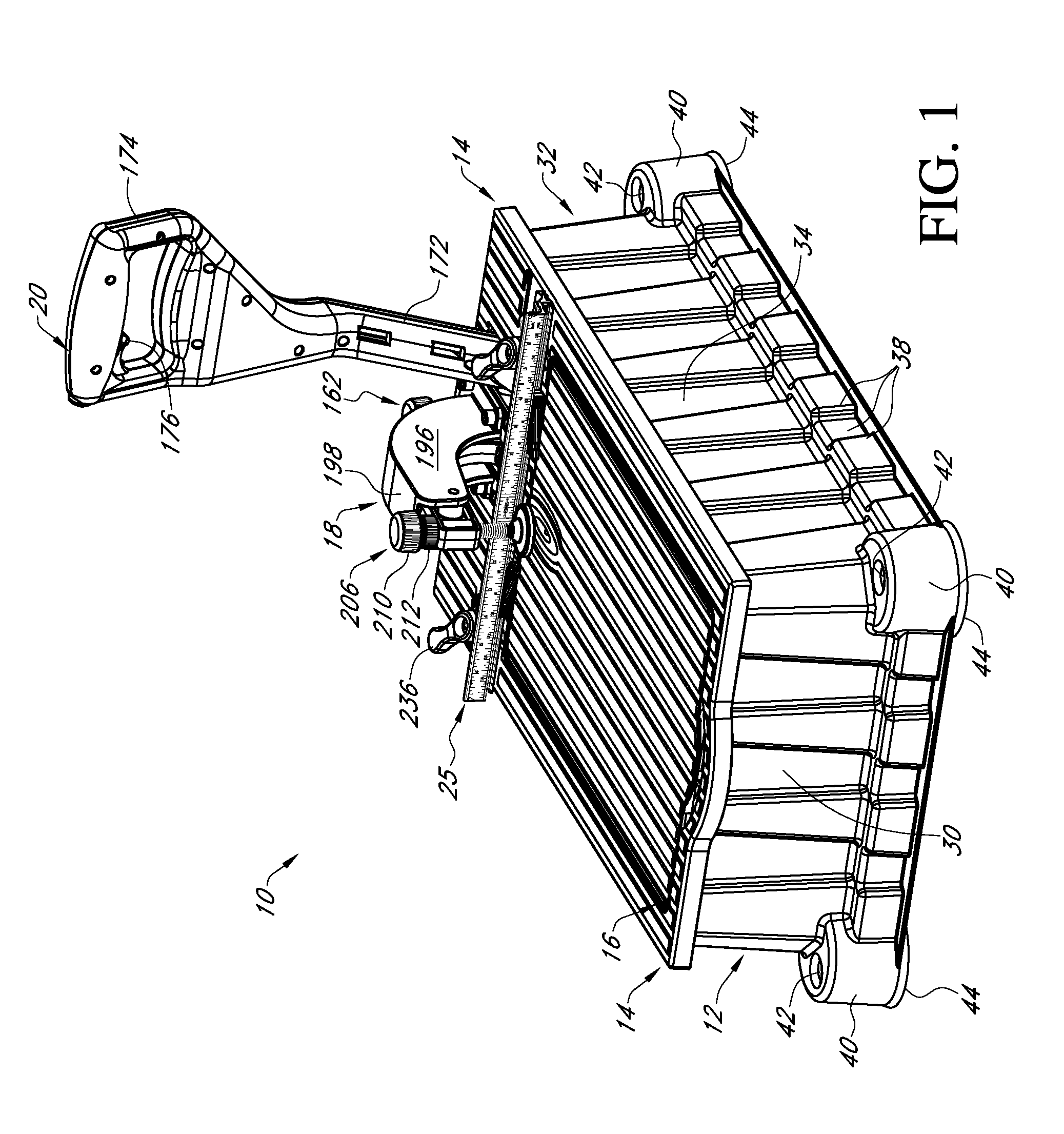
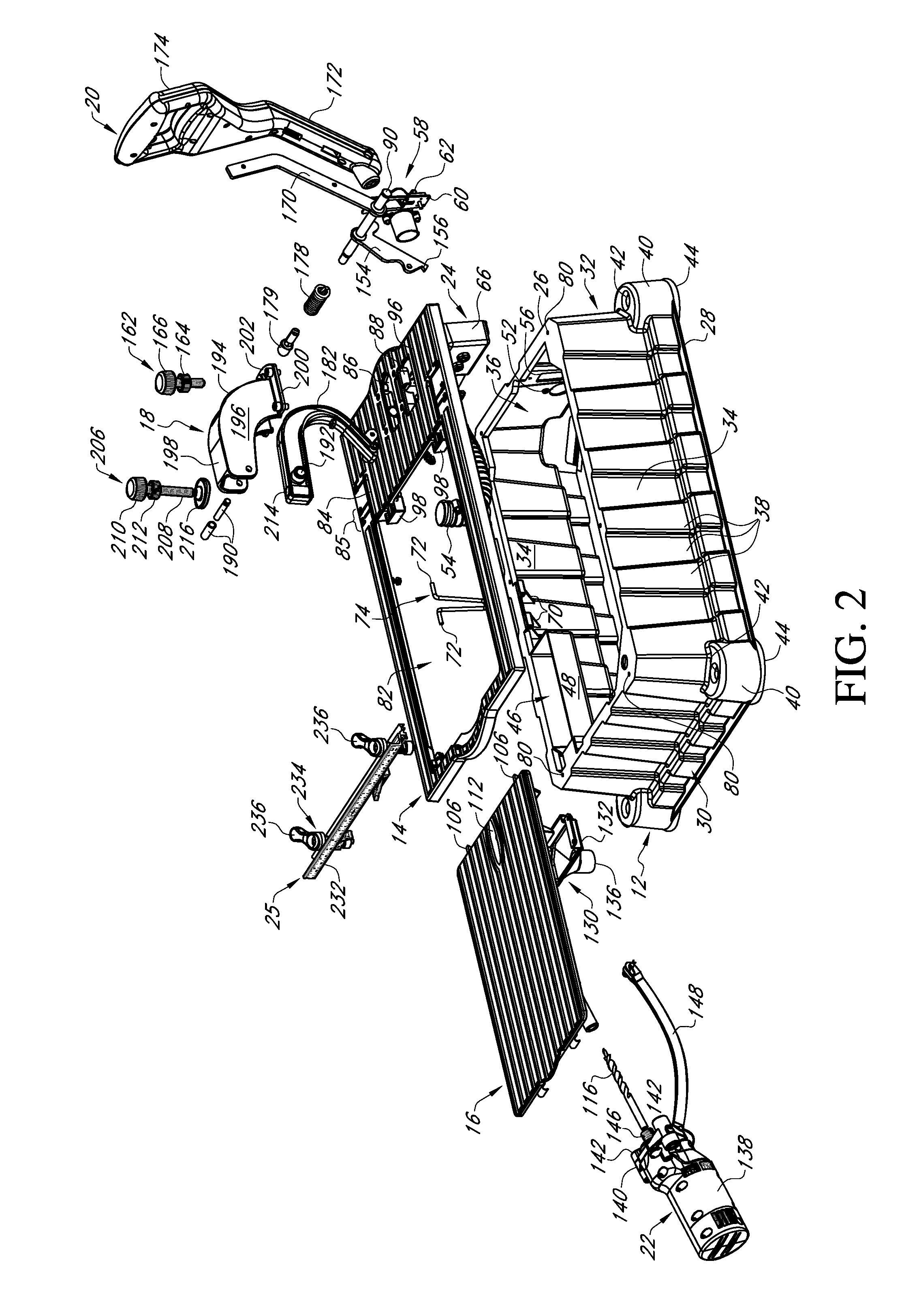
  • Cam lock fence system and method of use
  • Cam lock fence system and method of use
  • Cam lock fence system and method of use

Examples


Embodiment Construction

[0046]In the following detailed description, reference is made to the accompanying drawings which form a part hereof, and in which is shown by way of illustration specific embodiments in which the invention may be practiced. These embodiments are described in sufficient detail to enable those skilled in the art to practice the invention, and it is to be understood that other embodiments may be utilized and that mechanical, procedural, and other changes may be made without departing from the spirit and scope of the invention(s). The following detailed description is, therefore, not to be taken in a limiting sense, and the scope of the present invention is defined only by the appended claims, along with the full scope of equivalents to which such claims are entitled.

[0047]As used herein, the terminology such as vertical, horizontal, top, bottom, front, back, ends, sides, etc., are referenced according to the views presented. It should be understood, however, that the terms are used on...


PUM

PropertyMeasurementUnit
Forceaaaaaaaaaa
Areaaaaaaaaaaa

Abstract

A cam lock connected with a fence assembly includes a handle portion, a top carrier and a bottom carrier connected by a threaded shaft. The handle portion and top carrier are positioned above the fence assembly and a work table or surface; wherein the bottom carrier is positioned below the fence assembly and work table or surface. The top carrier and bottom carrier both have a pair of alignment arms with a space positioned therebetween, the alignment arms of the top carrier nest with the alignment arms of the bottom carrier. The handle portion and top carrier both have cam surfaces that engage one another such that when the handle portion is rotated around the axis of the threaded shaft the handle portion is raised or lowered thereby raising or lowering the bottom carrier, thereby locking or unlocking the fence assembly in a quick, durable, easy and accurate manner.

Description

CROSS REFERENCE TO RELATED APPLICATION[0001]This application claims the benefit of U.S. Provisional Application No. 61 / 833,487 filed Jun. 11, 2013.FIELD OF THE INVENTION[0002]This invention relates to stop and alignment systems. More specifically, and without limitation, this invention relates to a stop and alignment systems for woodworking devices.BACKGROUND OF INVENTION[0003]There are many types of stop and alignment systems designed for use with machines in use today. These stop and alignment systems are used in association with countless types of machines such as for example, a table saw, drill press, miter saw, ban saw, router table, bench rest, radial arm saw, or the like and they are used to align a work piece for machining processes like drilling, cutting, routing or the like.[0004]While these stop and alignment systems are functional, many of them suffer from substantial disadvantages. Namely, many conventional stop and alignment systems are expensive to produce or are form...

Claims


Application Information

Patent Timeline
IPC IPC(8): B23B47/00B23Q3/18
CPCB23Q3/18B23B47/00B27B27/00B27C3/02B27C3/08B25B5/08B25B5/06B25B11/00B23B2247/10B23B2247/12B23B47/288Y10T408/563Y10T408/03B23B39/003B23B41/00
Inventor CLARK, SCOTT L.
Owner KREG ENTERPRISES
Learn More