Steam power plant turbine and control method for operating at low load

a technology of steam power plant and control method, which is applied in the direction of steam engine plant, machine/engine, mechanical equipment, etc., can solve the problems of reducing cycle efficiency, reducing energy utilization and efficiency, and not providing an increase in the pressure of the reheat system

Active Publication Date: 2014-12-18
GENERAL ELECTRIC TECH GMBH
View PDF24 Cites 21 Cited by
  • Summary
  • Abstract
  • Description
  • Claims
  • Application Information

AI Technical Summary

Benefits of technology

[0010]According to aspects illustrated herein, there is provided, a system for effecting pressure control in a thermal power plant operated at low load connected fluidly in series. The plant comprises a boiler for burning fossil fuel to generate steam; a steam turbine including a high-pressure turbine, an intermediate pressure turbine, and a low pressure turbine which are driven by steam generated in the boiler; a main steam conduit for feeding steam from the boiler to an inlet of the high pressure turbine; and a cold reheat conduit for feeding steam from an outlet of the high-pressure turbine through a reheat flow path in the boiler. The cold reheat conduit operatively connected to a hot reheat conduit for feeding reheat steam to an inlet of intermediate pressure turbine. The further includes a crossover conduit for feeding steam from an outlet of the intermediate turbine to a low pressure turbine; and a low pressure exhaust conduit operatively

Problems solved by technology

During the operation of steam turbines in a boiler fired power, often there is a need to run turbines at low load levels for extended periods of times. Conventional steam power plants are designed to operate at rated load, and thus operation at low load level results in a decrease in energy utilization and efficiency.
Further, with a reduced reheat pressure, the temperature at the outlet of the hot reheat system will drop, resulting into reduced cycle efficiency.
This solution, however, requir

Method used


Image

  • Steam power plant turbine and control method for operating at low load
  • Steam power plant turbine and control method for operating at low load
  • Steam power plant turbine and control method for operating at low load

Examples


Embodiment Construction

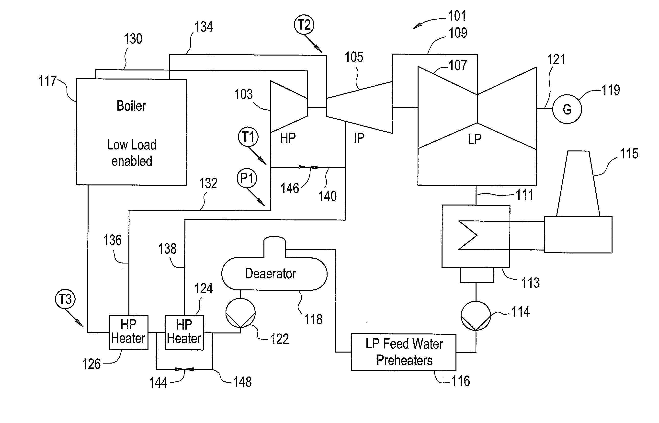
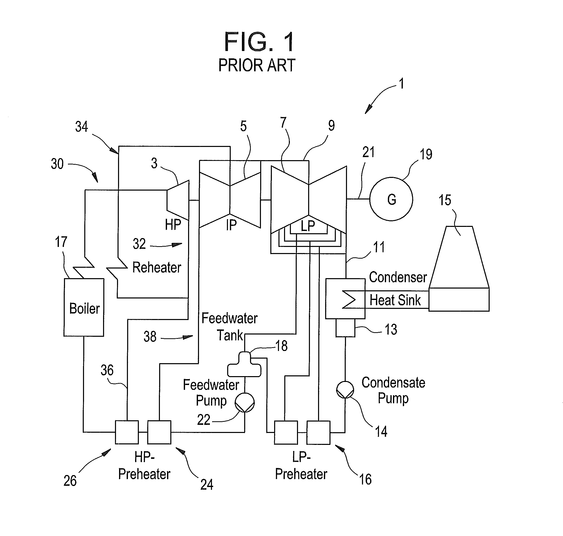
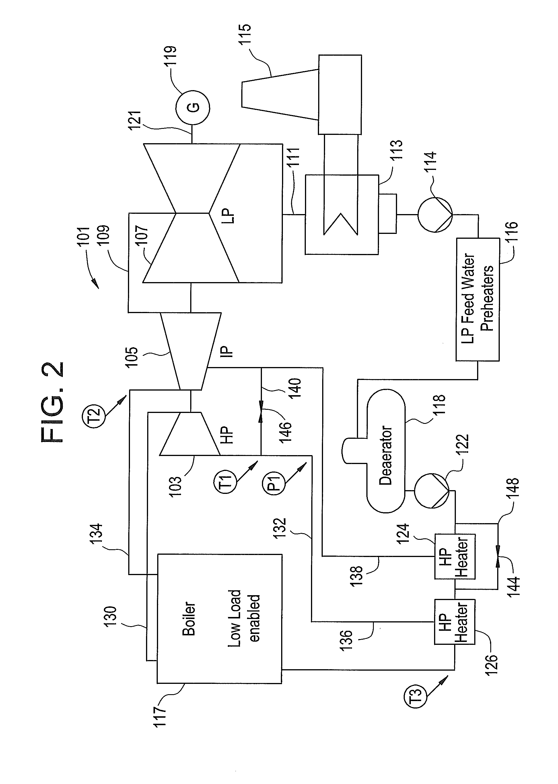
[0019]FIG. 1 shows a schematic view illustrating a prior art conventional power plant with three or more steam turbines. In this exemplary embodiment, the steam turbine 1 is of the multi-pressure single shaft type and comprises a high-pressure turbine 3, an intermediate pressure turbine 5, and a low pressure turbine 7 (also abbreviated herein as HP, IP, and LP), which are driven to rotate by the steam generated by a boiler 17, a generator 19 for converting the turning force of the steam turbine to electric power, a condenser 13, for condensing the steam to water, and a water feed system for feeding the feedwater condensed to the water by the condenser 13 to the boiler 17.

[0020]The high-pressure turbine 3, the intermediate-pressure turbine 5, the low-pressure turbine 7, and the generator 19 are connected to each other via a turbine rotor 21 and the electric power of each turbine is transferred to the generator 19 via the turbine rotor 21 and is taken out as electric power.

[0021]The b...


PUM


Abstract

In a system for effecting pressure control in a thermal power plant operated at low load connected fluidly in series, a relief conduit is disclosed herein. The relief conduit selectively transfers steam from a cold reheat conduit to the second extraction conduit. The plant further includes a boiler, a high-pressure turbine, an intermediate pressure turbine, a low pressure turbine, a main steam conduit for feeding steam from the boiler to an inlet of the high pressure turbine, a cold reheat conduit for feeding steam from an outlet of the high-pressure turbine through a reheat flow path in the boiler, and a first and second high pressure heaters. A first extraction conduit connects the cold reheat conduit to a first high pressure heater to transfer heat, and a second extraction conduit connects the intermediate pressure turbine to the second high pressure heater, to transfer heat.

Description

FIELD OF THE INVENTION[0001]The present disclosure relates, in general, to a thermal power plant and more particularly to a fossil fuel combustion thermal power plant including a steam turbine and a control method for a thermal power plant frequently operated at low load.BACKGROUND OF THE INVENTION[0002]During the operation of steam turbines in a boiler fired power, often there is a need to run turbines at low load levels for extended periods of times. Conventional steam power plants are designed to operate at rated load, and thus operation at low load level results in a decrease in energy utilization and efficiency.[0003]When the load of a steam turbine is reduced, pressure in the reheat system drops in direct proportion to the steam flow. Reheat pressure is a sensitive parameter in a power plant. This is because in most steam power plants the highest feedwater heater is connected to the cold reheat system. The cold reheat pressure is directly related to the feedwater temperature a...

Claims


Application Information

Patent Timeline
IPC IPC(8): F01K11/02
CPCF01K11/02F01K7/24F01K7/345F01K7/40F01K13/02
Inventor HELLWEG, STEPHANSCHULE, VOLKERBAUER, MANFRED
Owner GENERAL ELECTRIC TECH GMBH
Why Eureka
Try Eureka