Method and apparatus for determining a focal position of an imaging device adapted to image a biologic sample

a technology for imaging devices and biologic samples, applied in closed circuit television systems, instruments, television systems, etc., can solve the problems of inability to hold the mechanical tolerances of the sample holder to these dimensions, time-consuming multiple image processes, and inability to achieve the desired effect, and achieve the effect of more robust methods and apparatus

Inactive Publication Date: 2014-12-18
ABBOTT POINT CARE
View PDF2 Cites 26 Cited by
  • Summary
  • Abstract
  • Description
  • Claims
  • Application Information

AI Technical Summary

Benefits of technology

[0010]The present method and apparatus present numerous advantages over currently available biologic sample imaging and analysis technology. For example, the present invention provides an inexpensive means of ensuring rapid focusing of a biologic sample that is consistently accurate, one that can be used in a variety of imaging system configurations, and one that relies only on the imaging system itself. The present invention also can typically determine from a single image whether or not the imaging system is in perfect exposure, and if not, the present invention can often determine the exact amount of movement required to bring sample image into perfect focus. The present invention also provides an imaging method and apparatus that is insensitive to the actual exposure or image light intensity, and thereby provides a more robust method and apparatus.

Problems solved by technology

Re-focusing is necessary because the required precision of focus for such systems, at useful magnifications, can be as little as one micron and it is virtually impossible to hold the mechanical tolerances of the sample holder to these dimensions.
This multiple image process is time consuming and therefore not desirable.
In the second case, the independent device typically adds complication and considerable expense to the imaging system.

Method used


Image

  • Method and apparatus for determining a focal position of an imaging device adapted to image a biologic sample
  • Method and apparatus for determining a focal position of an imaging device adapted to image a biologic sample
  • Method and apparatus for determining a focal position of an imaging device adapted to image a biologic sample

Examples


example

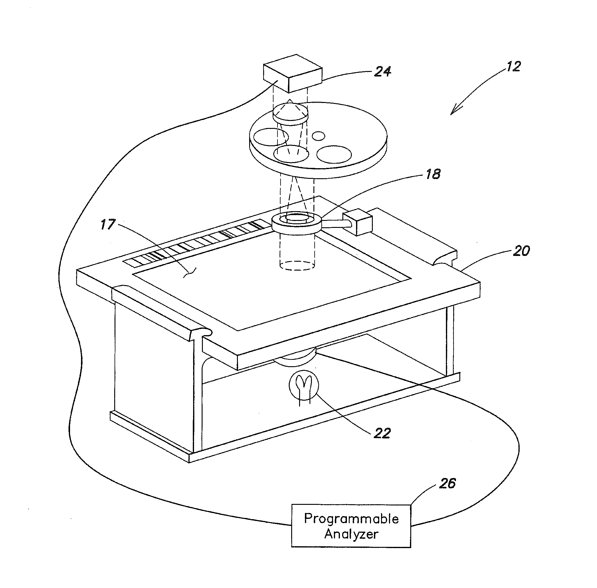
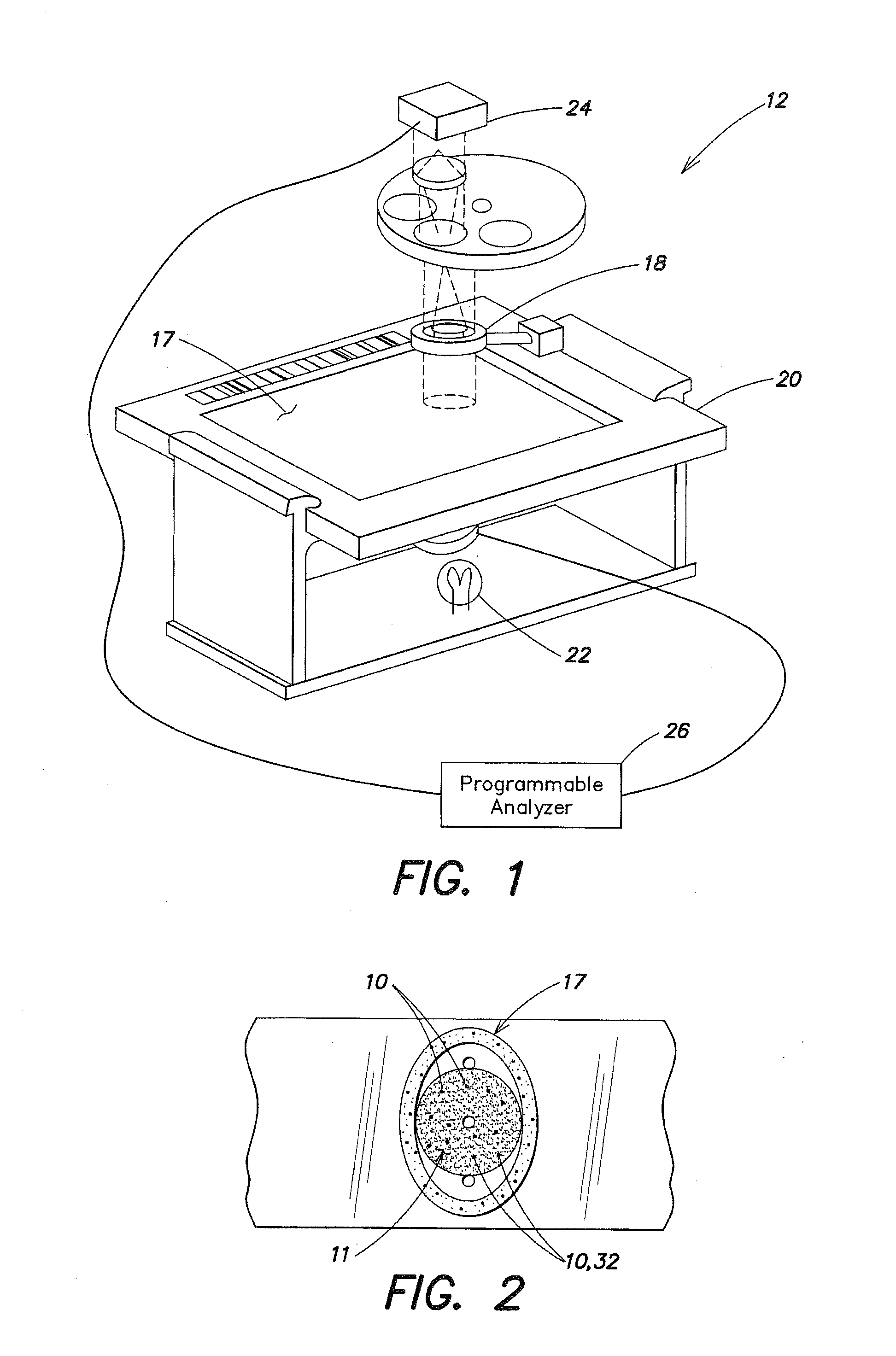
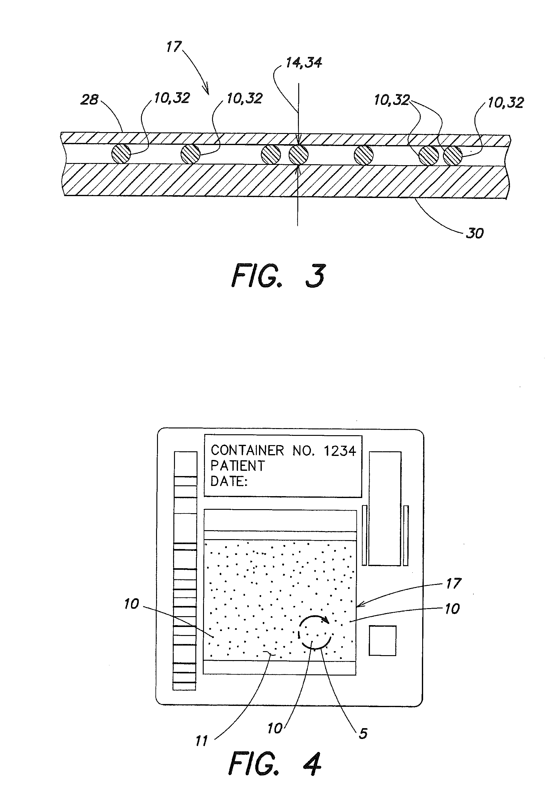
[0034]The following is an illustrative example of focusing an imaging device 12 according to the present method. FIG. 8 provides a block diagram according to a method aspect of the present invention. The invention is not, however, limited to this example.

[0035]A sample 11 of biologic fluid (e.g., substantially undiluted anticoagulated whole blood), is deposited within a chamber 17. A number of lenslets 10 are positioned relative to the sample 11 in a manner such that they will remain at a fixed distance from the point in the sample 11 where best focus is required for the duration of the analysis. The number of lenslets 10 can vary depending upon the application, but there should be enough such that there are a sufficient number of lenslets 10 in each field of view to accurately practice the method (e.g., a number of lenslets 10 great enough so that statistically acceptable average light transmittance intensity values can be calculated, etc.). The lenslets 10 may be dispersed randoml...


PUM


Abstract

A method and apparatus for focusing a device for imaging a biologic sample is provided. A method aspect includes the steps of: disposing lenslets within a biologic sample, which lenslets have a height and a refractive index, which refractive index is different from that of the sample, wherein one or both of the imaging device and the sample are relatively locatable so a focal position of the imaging device can be moved along the height of the lenslets; imaging a portion of the sample including lenslets using transmittance at one or more wavelengths; determining an average light transmittance intensity of the sample at the wavelengths; determining an average light transmittance intensity of a region of each lenslet at the wavelengths; and determining the focal position of the imaging device using the average light transmittance intensity of the sample and the average light transmittance intensity of the region of the lenslets.

Description

[0001]The present application is a divisional of U.S. patent application Ser. No. 13 / 279,991 filed Oct. 24, 2011, which is a continuation of U.S. patent application Ser. No. 12 / 408,479 filed Mar. 20, 2009, which claims priority to and incorporates by reference essential subject matter disclosed in U.S. Provisional Patent Application Ser. No. 61 / 038,572, filed Mar. 21, 2008.BACKGROUND OF THE INVENTION[0002]1. Technical Field[0003]The present invention relates to imaging biologic samples in general, and to focusing the image of biologic samples in particular.[0004]2. Background Information[0005]Automated microscopy systems that take multiple images over the surface of a biologic sample generally require the imaging system to be re-focused for each field imaged. Re-focusing is necessary because the required precision of focus for such systems, at useful magnifications, can be as little as one micron and it is virtually impossible to hold the mechanical tolerances of the sample holder t...

Claims


Application Information

Patent Timeline
Patent Type & Authority Applications(United States)
IPC IPC(8): G02B21/36
CPCG02B21/365G02B21/361G02B21/244
Inventor WARDLAW, STEPHEN C.LALPURIA, NITEN V.UNFRICHT, DARRYN W.
Owner ABBOTT POINT CARE
Why Eureka
Try Eureka