
Methods and apparatuses for encoding and decoding video using temporal motion vector prediction

Active Publication Date: 2014-12-18
SUN PATENT TRUST
View PDF2 Cites 14 Cited by
  • Summary
  • Abstract
  • Description
  • Claims
  • Application Information

AI Technical Summary

Benefits of technology

This patent provides methods and devices for making videos by using motion vectors to predict the movement of objects in consecutive pictures. The invention improves the accuracy and flexibility of this prediction, making it possible to turn off motion vectors for individual parts of a video while still getting good results overall. This leads to better coding efficiency and flexibility for video production.

Problems solved by technology

In applications requiring video transmission across lossy environment, temporal motion vector prediction is susceptible to erroneous prediction of motion vector when the collocated reference picture is lost or contains errors.

Method used


Image

  • Methods and apparatuses for encoding and decoding video using temporal motion vector prediction
  • Methods and apparatuses for encoding and decoding video using temporal motion vector prediction
  • Methods and apparatuses for encoding and decoding video using temporal motion vector prediction

Examples


embodiment a

[0127]The processing described in each of embodiments can be simply implemented in an independent computer system, by recording, in a recording medium, a program for implementing the configurations of the moving picture coding method (image coding method) and the moving picture decoding method (image decoding method) described in each of embodiments. The recording media may be any recording media as long as the program can be recorded, such as a magnetic disk, an optical disk, a magnetic optical disk, an IC card, and a semiconductor memory.

[0128]Hereinafter, the applications to the moving picture coding method (image coding method) and the moving picture decoding method (image decoding method) described in each of embodiments and systems using thereof will be described. The system has a feature of having an image coding and decoding apparatus that includes an image coding apparatus using the image coding method and an image decoding apparatus using the image decoding method. Other c...

embodiment b

[0161]Video data can be generated by switching, as necessary, between (i) the moving picture coding method or the moving picture coding apparatus shown in each of embodiments and (ii) a moving picture coding method or a moving picture coding apparatus in conformity with a different standard, such as MPEG-2, MPEG-4 AVC, and VC-1.

[0162]Here, when a plurality of video data that conforms to the different standards is generated and is then decoded, the decoding methods need to be selected to conform to the different standards. However, since to which standard each of the plurality of the video data to be decoded conform cannot be detected, there is a problem that an appropriate decoding method cannot be selected.

[0163]In order to solve the problem, multiplexed data obtained by multiplexing audio data and others onto video data has a structure including identification information indicating to which standard the video data conforms. The specific structure of the multiplexed data including...

embodiment c

[0178]Each of the moving picture coding method, the moving picture coding apparatus, the moving picture decoding method, and the moving picture decoding apparatus in each of embodiments is typically achieved in the form of an integrated circuit or a Large Scale Integrated (LSI) circuit. As an example of the LSI, FIG. 27 illustrates a configuration of the LSI ex500 that is made into one chip. The LSI ex500 includes elements ex501, ex502, ex503, ex504, ex505, ex506, ex507, ex508, and ex509 to be described below, and the elements are connected to each other through a bus ex510. The power supply circuit unit ex505 is activated by supplying each of the elements with power when the power supply circuit unit ex505 is turned on.

[0179]For example, when coding is performed, the LSI ex500 receives an AV signal from a microphone ex117, a camera ex113, and others through an AV IO ex509 under control of a control unit ex501 including a CPU ex502, a memory controller ex503, a stream controller ex5...


PUM


Abstract

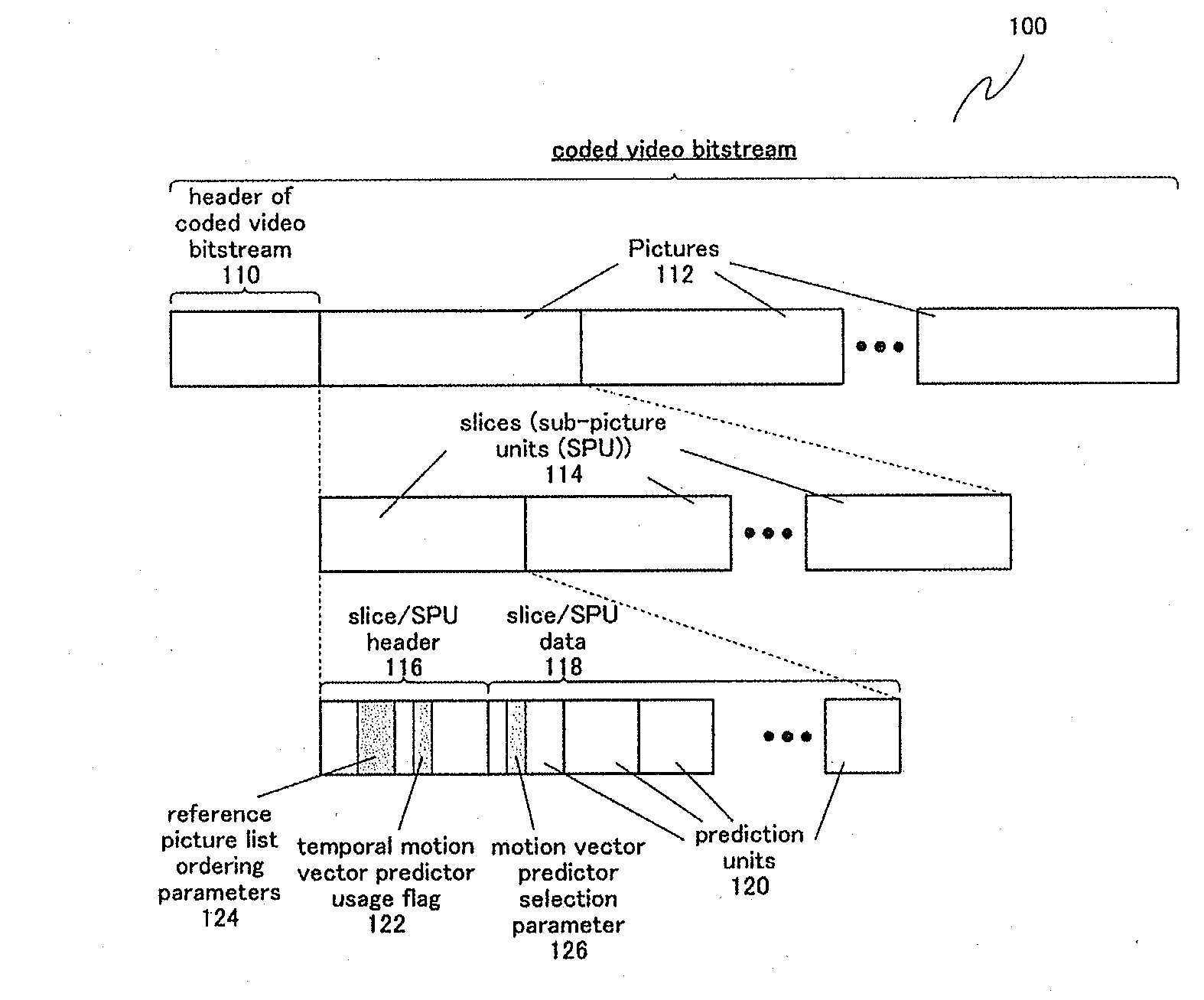
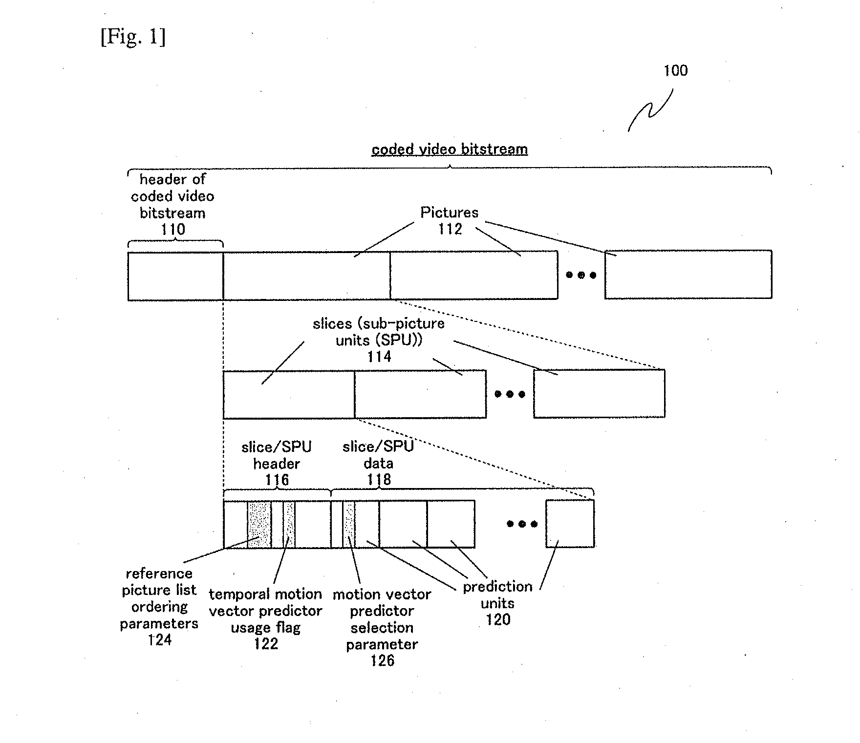
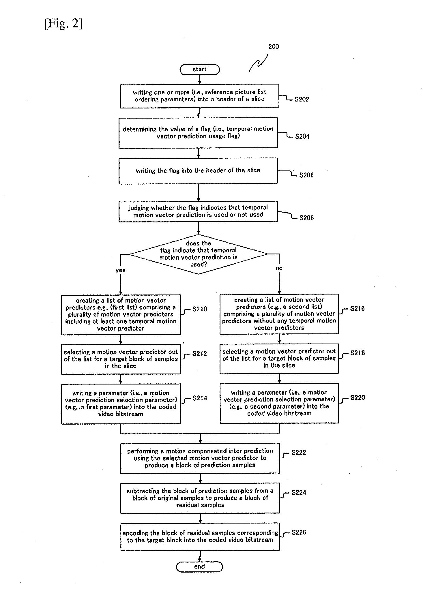
A method of encoding a video into a coded video bitstream with temporal motion vector prediction comprises: determining a value of a flag for indicating whether temporal motion vector prediction is used or not used for the inter-picture prediction of a sub-picture unit of a picture; and writing the flag having the value into a header of the sub-picture unit or a header of the picture; wherein if the flag indicates that temporal motion vector prediction is used, the method further comprises: creating a first list of motion vector predictors comprising a plurality of motion vector predictors including at least one temporal motion vector predictor derived from at least one motion vector from a collocated reference picture; selecting a motion vector predictor out of the first list; and writing a first parameter into the coded video bitstream for indicating the selected motion vector predictor out of the first list.

Description

TECHNICAL FIELD[0001]The present invention relates to a method of encoding a video and a method of decoding a video using temporal motion vector prediction, and apparatuses thereof. The present invention can be applied in any multimedia data coding and, more particularly, in coding of image and video contents utilizing temporal motion vector prediction for inter-picture prediction.BACKGROUND ART[0002]Video coding schemes, such as H.264 / MPEG-4 AVC and the upcoming HEVC (High-Efficiency Video Coding) perform encoding / decoding of image / video content using inter-picture (or simply “inter”) prediction from previously encoded / decoded reference pictures to exploit information redundancy across consecutive pictures in time.[0003]In a coded video bitstream, a reference picture used for the inter prediction process of a prediction unit (such as an M×N block of samples) is identified by or referred to using a reference index. A reference index is an index into an ordered list (known as a refer...

Claims


Application Information

Patent Timeline
IPC IPC(8): H04N19/51H04N19/89
CPCH04N19/00939H04N19/00696H04N19/159H04N19/31H04N19/52H04N19/577H04N19/61H04N19/70H04N19/105H04N19/184H04N19/46
Inventor NAING, SUE MON THETWAHADANIAH, VIKTORLIM, CHONG SOONSUN, HAI WEIWIN, KYAW KYAWNISHI, TAKAHIROSASAI, HISAOSHIBAHARA, YOUJISUGIO, TOSHIYASUTANIKAWA, KYOKOMATSUNOBU, TORUTERADA, KENGO
Owner SUN PATENT TRUST
Learn More