Assembly for mounting a turbine engine to a pylon
- Summary
- Abstract
- Description
- Claims
- Application Information
AI Technical Summary
Benefits of technology
Problems solved by technology
Method used
Image
Examples
Embodiment Construction
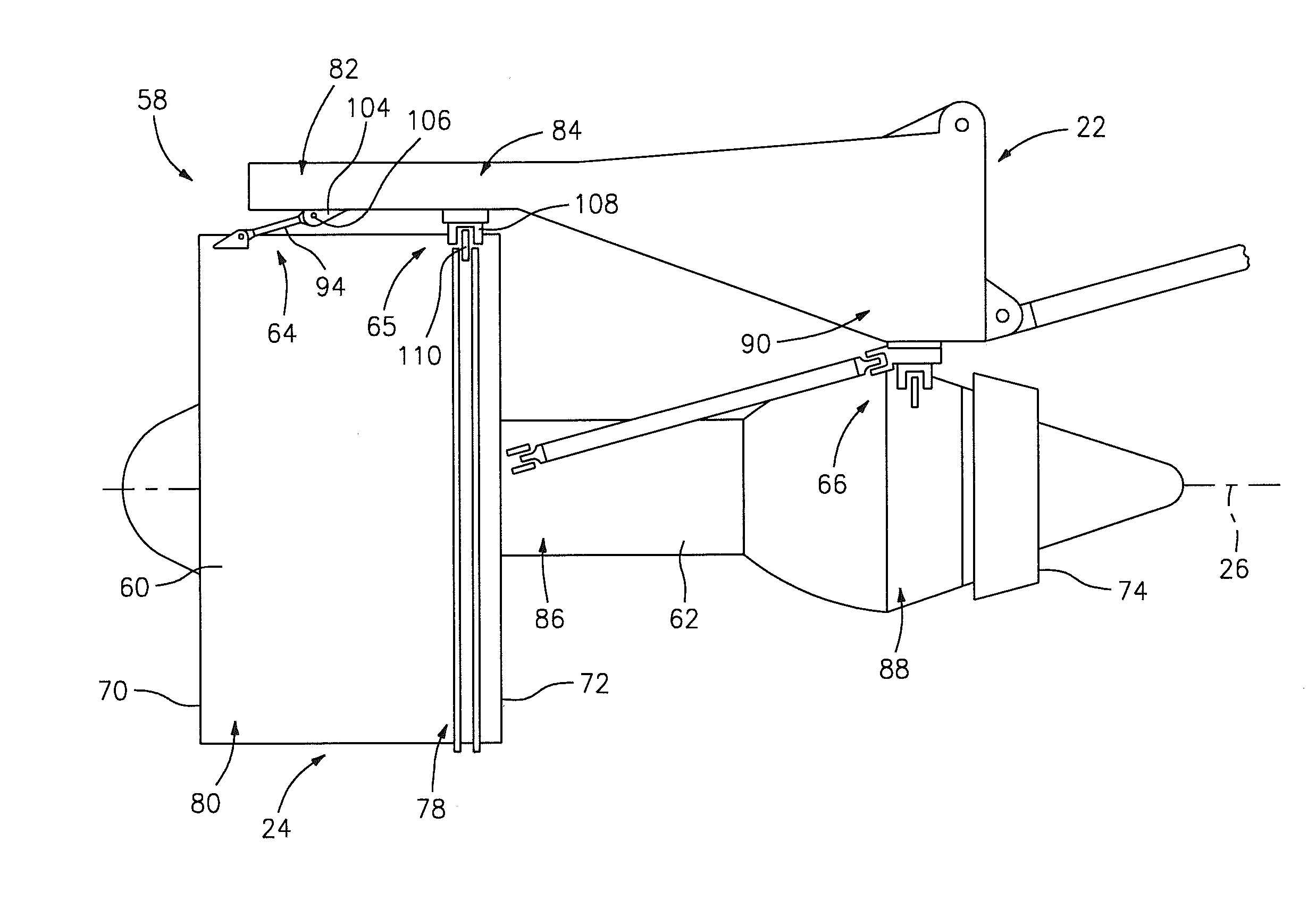
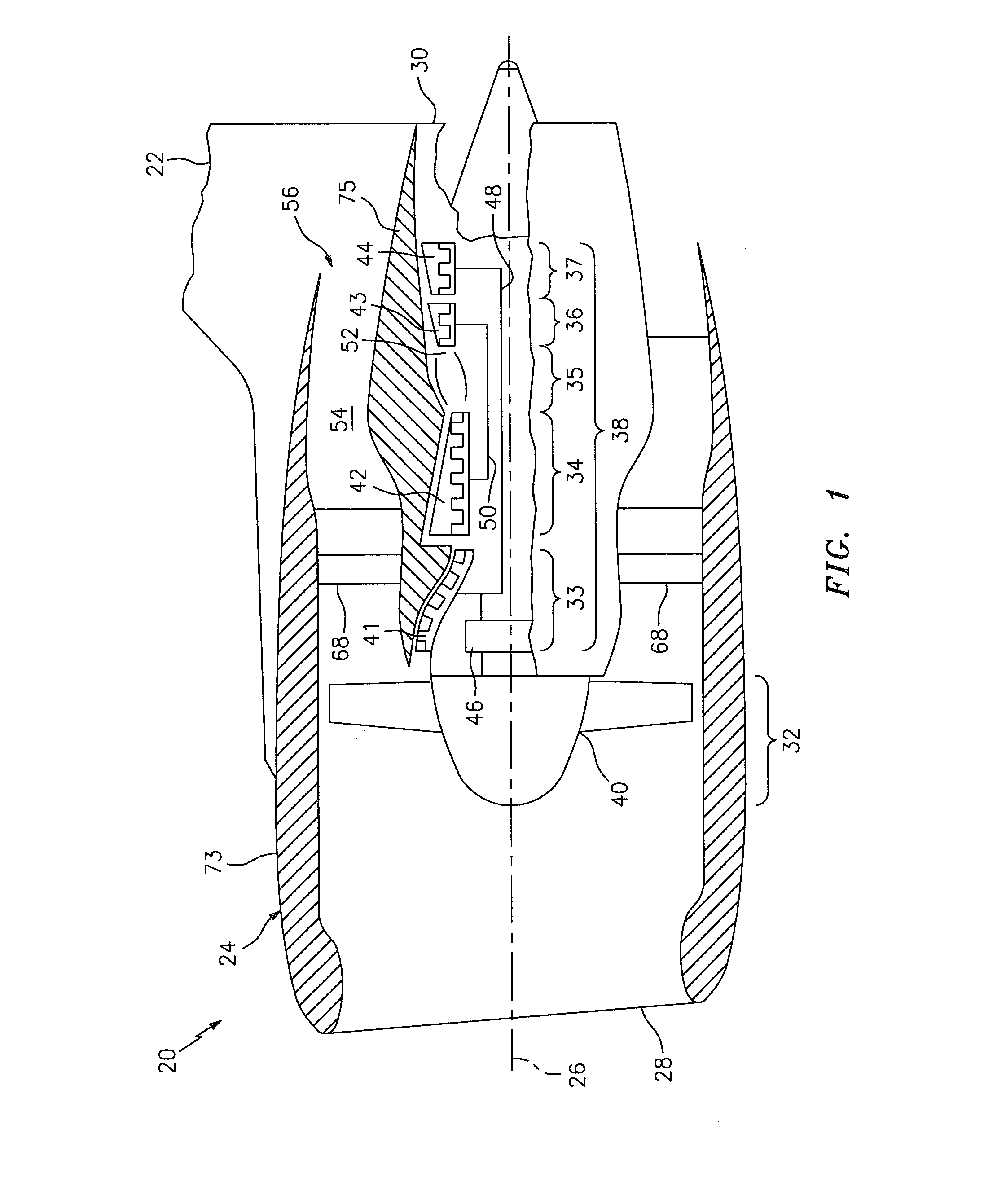
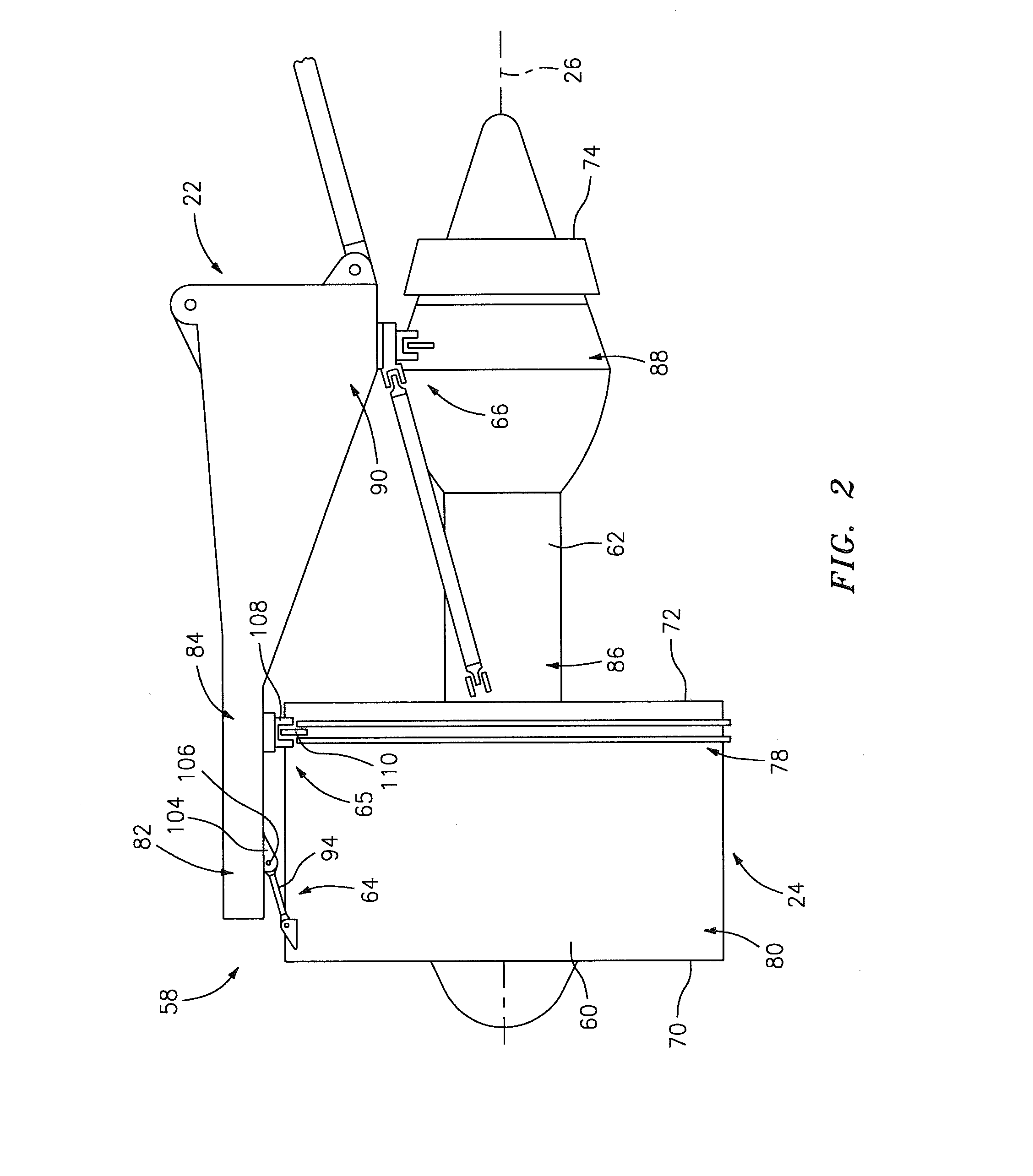
[0034]FIG. 1 is a side cutaway illustration of a turbine engine system 20. The turbine engine system 20 includes a pylon 22 and a turbine engine 24 (e.g., a propulsion system) such as, for example, a geared turbofan engine that uses outlet guide vanes (OGV) to structurally connect the fan module to the core engine module as well as redirect the incoming fan flow to the OGV. The turbine engine 24 is mounted to the pylon 22, which may be mounted to or otherwise configured with an aircraft airframe. Examples of an aircraft airframe include, but are not limited to, an aircraft wing or an aircraft fuselage.
[0035]The turbine engine 24 extends along an axial centerline 26 between a forward airflow inlet 28 and an aft airflow core exhaust 30. The turbine engine 24 includes a fan section 32, a low pressure compressor (LPC) section 33, a high pressure compressor (HPC) section 34, a combustor section 35, a high pressure turbine (HPT) section 36 and a low pressure turbine (LPT) section 37. Thes...
PUM
 Abstract
Description
Claims
Application Information
 - R&D
- Intellectual Property
- Life Sciences
- Materials
- Tech Scout
- Unparalleled Data Quality
- Higher Quality Content
- 60% Fewer Hallucinations
Browse by: Latest US Patents, China's latest patents, Technical Efficacy Thesaurus, Application Domain, Technology Topic, Popular Technical Reports.
© 2025 PatSnap. All rights reserved.Legal|Privacy policy|Modern Slavery Act Transparency Statement|Sitemap|About US| Contact US: help@patsnap.com


