Turbofan bypass duct air cooled fluid cooler installation

a technology of fluid cooler and bypass duct, which is applied in the direction of mechanical equipment, efficient propulsion technology, machines/engines, etc., can solve problems such as engine operation problems, and achieve the effect of facilitating heat exchang

Active Publication Date: 2011-01-04
PRATT & WHITNEY CANADA CORP
View PDF21 Cites 82 Cited by
  • Summary
  • Abstract
  • Description
  • Claims
  • Application Information

AI Technical Summary

Benefits of technology

[0006]In another aspect, the present invention provides a gas turbine engine which comprises a core engine; a bypass duct surrounding the core engine and adapted to direct a bypass air flow through the bypass duct; a heat exchanger defining a fluid passage, the heat exchanger being disposed within the bypass duct and being exposed to the bypass air flow; and means for increasing a local pressure differential of the bypass air flow between upstream and downstream locations with respect to the heat exchanger in order to facilitate heat exchange between the heat exchanger and the air flow.

Problems solved by technology

Without proper cooling, poor cooling and / or poor lubrication of gears and bearings result, which may cause problems for engine operation.

Method used


Image

  • Turbofan bypass duct air cooled fluid cooler installation
  • Turbofan bypass duct air cooled fluid cooler installation
  • Turbofan bypass duct air cooled fluid cooler installation

Examples


Embodiment Construction

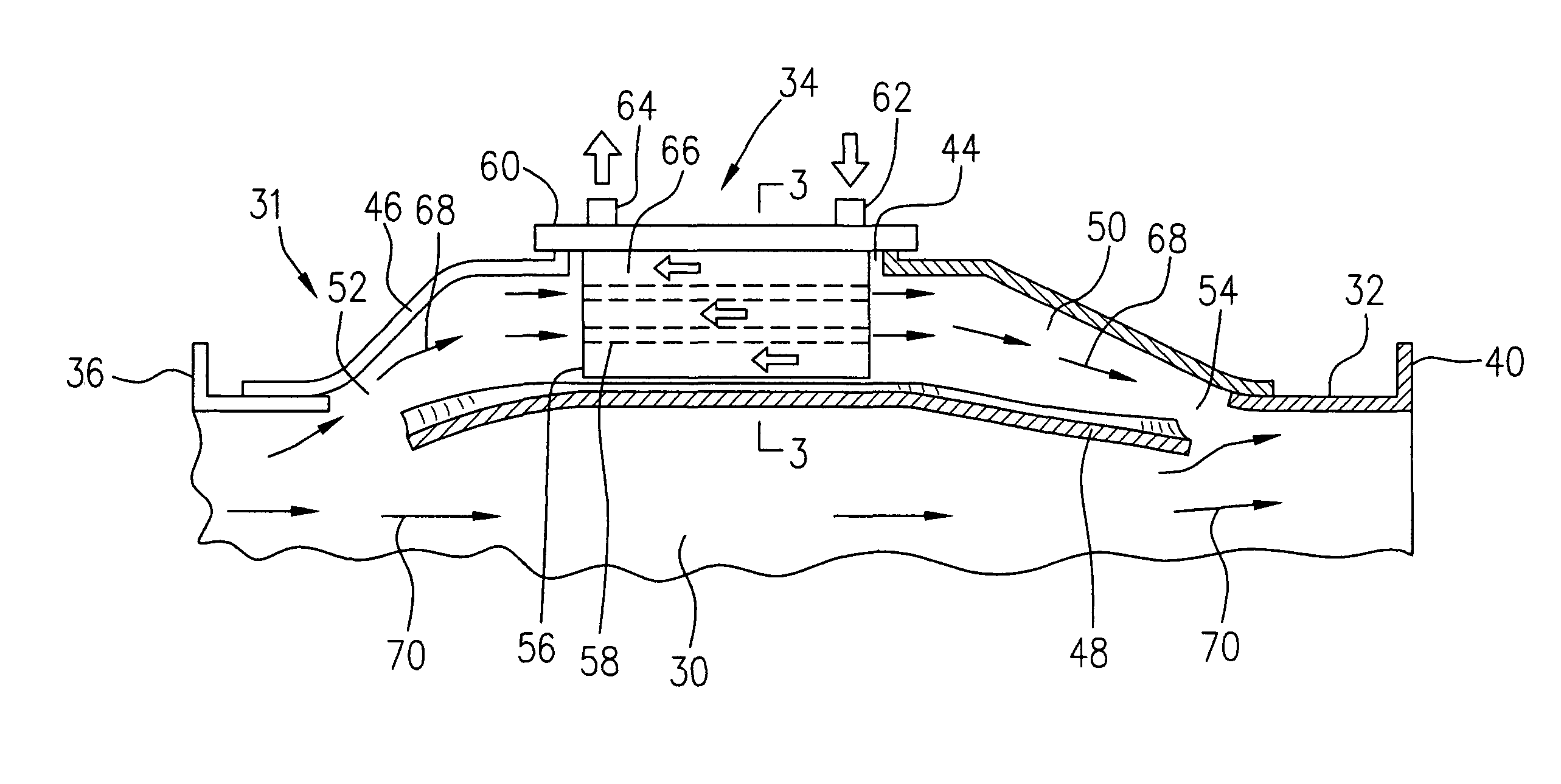
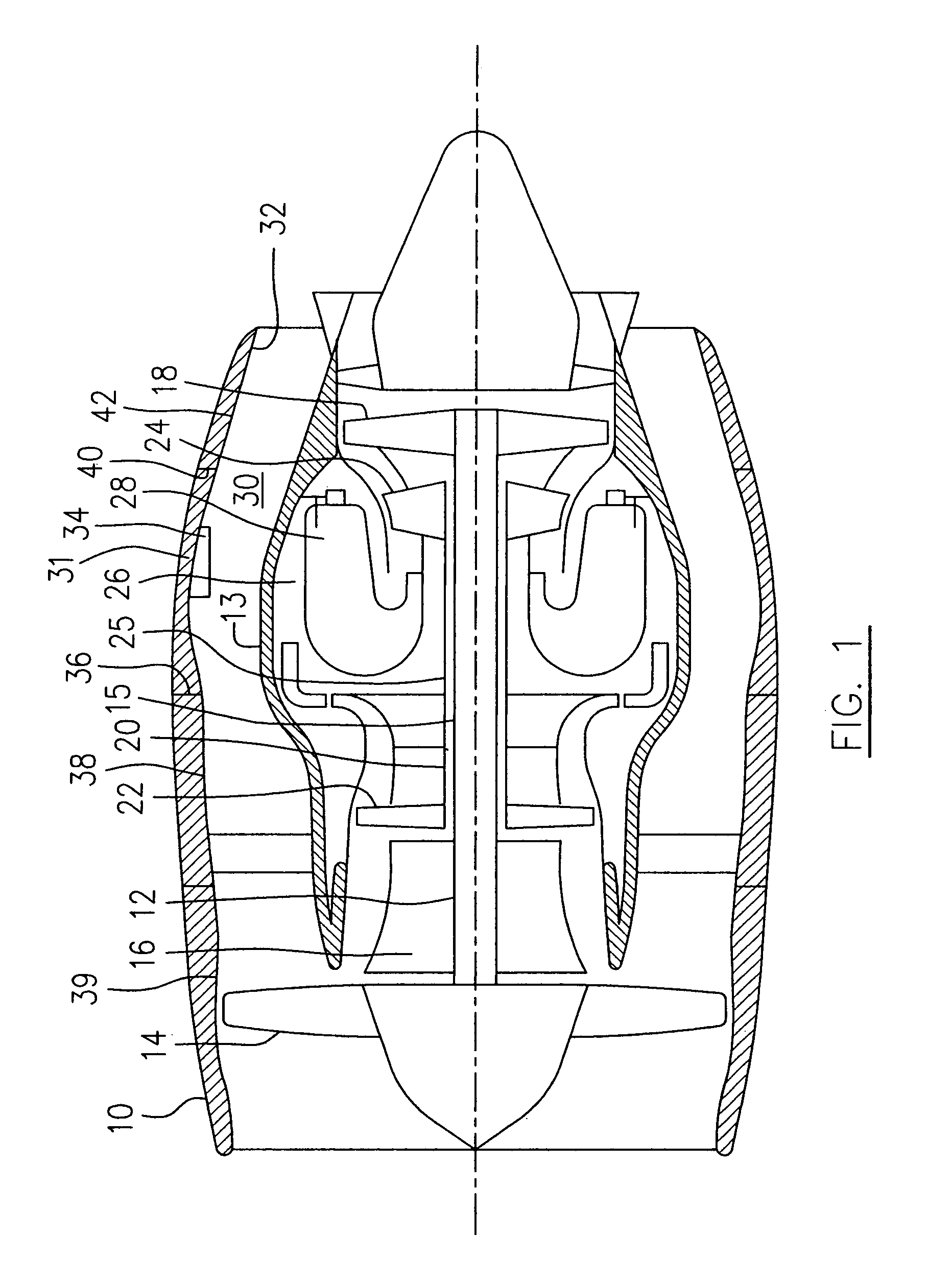
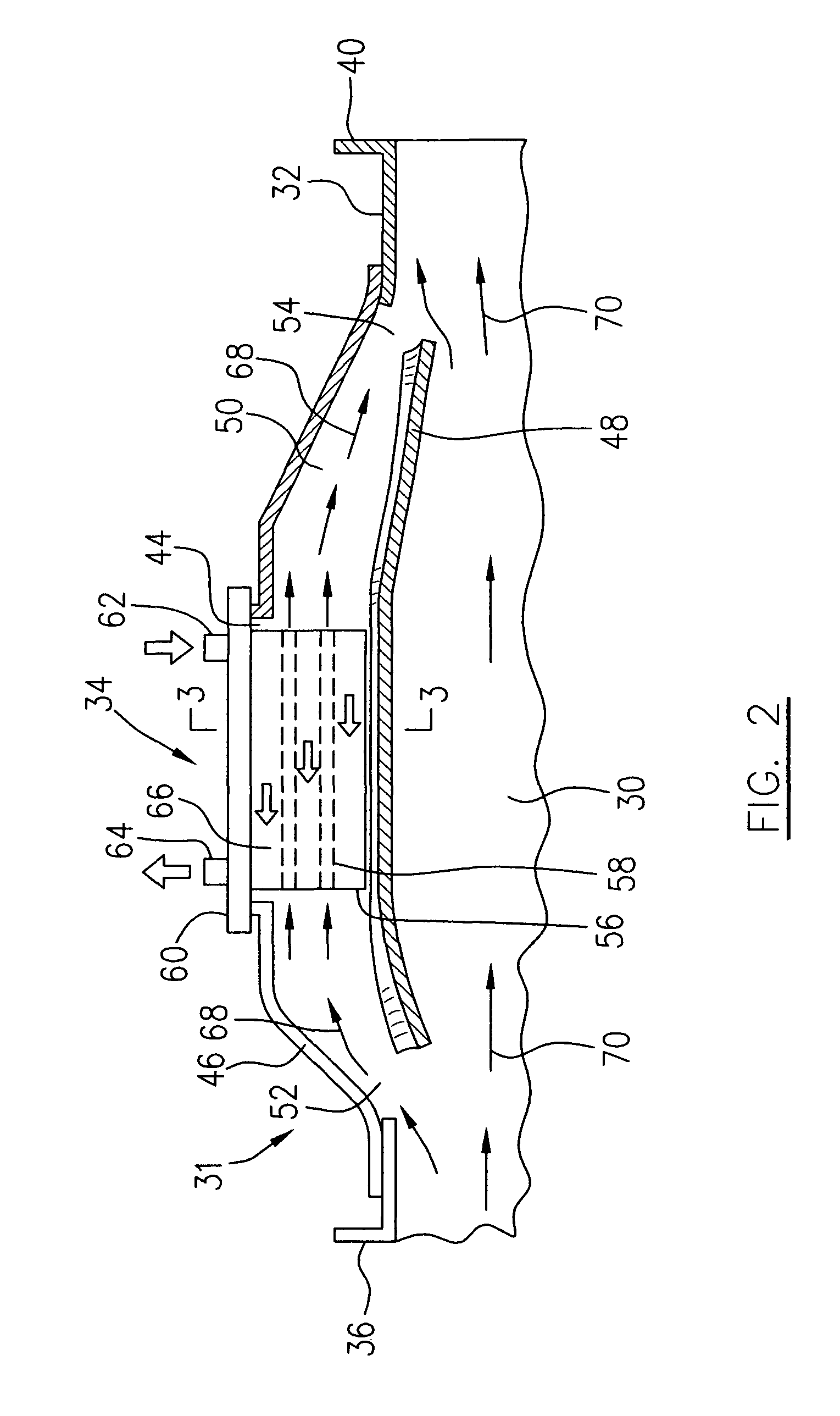
[0015]FIG. 1 illustrates a turbofan bypass gas turbine engine which includes a housing 10, a core casing 13, a low pressure spool assembly seen generally at 12 which includes a shaft 15 interconnecting a fan assembly 14, a low pressure compressor 16 and a low pressure turbine assembly 18, and a high pressure spool assembly seen generally at 20 which includes a shaft 25 interconnecting a high pressure compressor assembly 22 and a high pressure turbine assembly 24. The core casing 13 surrounds the low and high pressure spool assemblies 12 and 20 to define a main fluid path (not indicated) through the engine. In the main fluid path there is provided a combustion section 26 having a combustor 28 therein. An annular bypass duct 30 is defined between an inner bypass duct wall, formed for example by the core casing 13, and an outer bypass duct wall 32 formed by an outer bypass duct casing located within the housing 10. A stream of bypass air which is compressed by the fan assembly 14, is d...


PUM


Abstract

A cooling apparatus for cooling a fluid in a bypass gas turbine engine comprises a heat exchanger disposed within a bypass duct and accommodated by a sub-passage defined by a flow divider affixed to an annular wall of the bypass duct. The sub-passage defines an open upstream end and an open downstream end to direct a portion of the bypass air flow to pass therethrough.

Description

TECHNICAL FIELD[0001]The invention relates generally to gas turbine engines and more particularly, to an improved cooling apparatus for cooling of a fluid used in a turbofan bypass gas turbine engine.BACKGROUND OF THE INVENTION[0002]Lubricating oil used in aircraft gas turbine engines must be cooled. Without proper cooling, poor cooling and / or poor lubrication of gears and bearings result, which may cause problems for engine operation. In addition to employing conventional radiator-type oil coolers, the prior art also describes directing oil through inlet guide vanes or support struts to achieve a cooling benefit from air ingested by the engine. The cooling of engine fluid is also achieved by directing the fluid flowing directly along a surface defining a periphery of a bypass duct of a turbofan bypass gas turbine engine, to thereby permit heat exchange between the fluid and bypass air passing through the bypass duct. However, efforts have been made to further improve the cooling of...

Claims


Application Information

Patent Timeline
Patent Type & Authority Patents(United States)
IPC IPC(8): F02K3/02
CPCF02C7/14F02C7/141F02K3/04F05D2260/20Y02T50/676Y02T50/60
Inventor OLVER, BRYANCIAMPA, ALESSANDROMARRANO, ROBERTOTREPANIER, RICHARDLAMARRE, SYLVAINBERNARD, MARTINGERMAIN, PATRICK
Owner PRATT & WHITNEY CANADA CORP
Why Eureka
Try Eureka