Apparatus for mixing viscous material

Active Publication Date: 2007-07-12
LG CHEM LTD
View PDF43 Cites 20 Cited by
  • Summary
  • Abstract
  • Description
  • Claims
  • Application Information

AI Technical Summary

Benefits of technology

[0029] In addition, it is preferred that the sweeping impeller has constant thickness and width, and while being rotated, the sweeping impeller allows an edge thereof in a width direction to separate the viscous material adhered to the inner circumference of the sidewall of the chamber and the outer circumference of the draft tube from an adhesion surface, thereby promoting heat exchange between the corresponding adhesion surface and the heat medium.
[0030] Also preferably, an upper end of the sweeping impeller is fixed to the rotating rod

Problems solved by technology

However, if the polymer material is adhered to the wall of the chamber due to their viscosity, the heat of coolant or heating agent is not easily transferred into the chamber.
In severe cases, it may be impossible to produce a polymer product including a heat-sensitive reaction process.
However, the conventional mixing device 11 shows low heat exchange efficiency in areas except the inner circumference of the draft tube 19 (e.g., the outer circumference of the draft tube or the inner circumference of the sidewall).
If the high-viscosity material Z is not adhered to the heat exchange path, the supplied heat may pass through only the sidewalls 13b, 19a and be transferred more deeply into the high-viscosity material Z. However, sin

Method used


Image

  • Apparatus for mixing viscous material
  • Apparatus for mixing viscous material
  • Apparatus for mixing viscous material

Examples


Example

[0041] Hereinafter, preferred embodiments of the present invention will be described in detail with reference to the accompanying drawings. In the drawings, the same reference numeral denotes the same component having the same function.

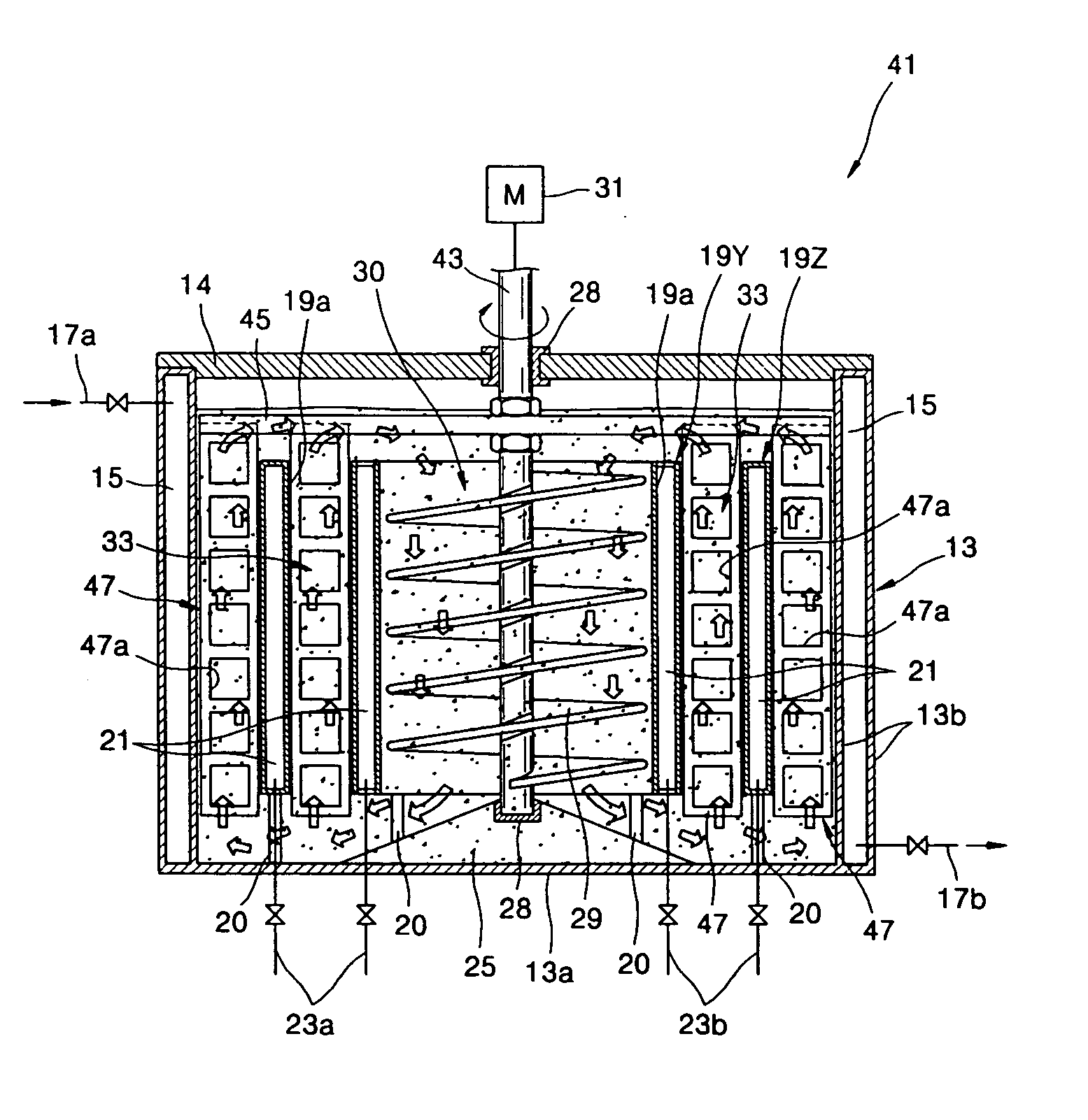
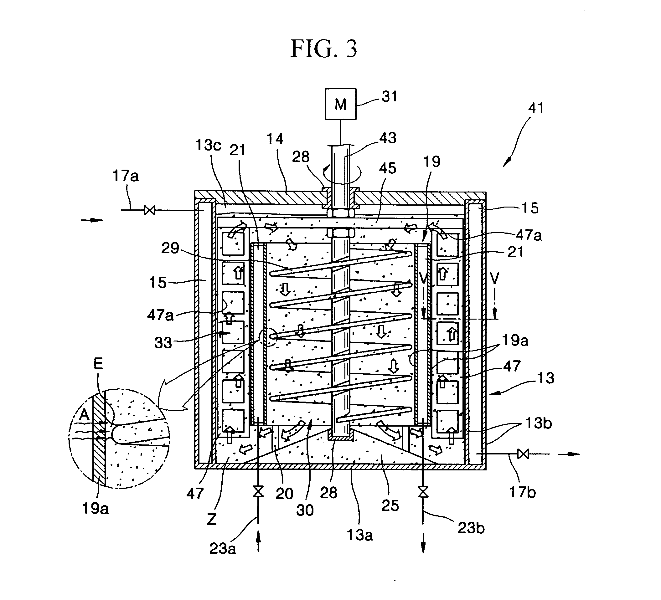
[0042]FIG. 3 is a sectional view showing an apparatus for mixing viscous material according to an embodiment of the present invention.

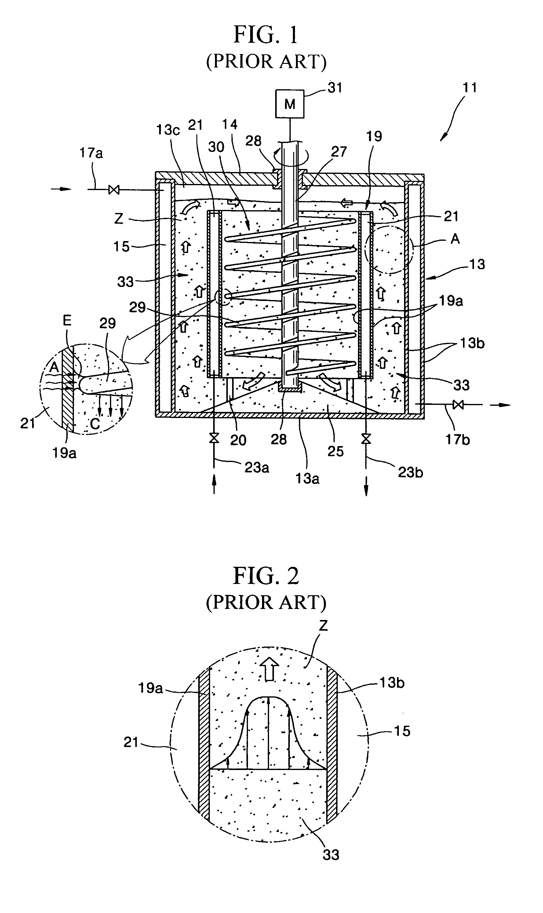
[0043] Referring to FIG. 3, the viscous material mixing apparatus 41 of this embodiment includes a chamber 13 for receiving high-viscosity material Z to be mixed, a draft tube 19 fixed in the chamber 13 and having a lower end spaced apart from a bottom 13a of the chamber 13, and a carrying impeller 30 installed to an inside of the draft tube 19 and driven by an external motor 31 to push the high-viscosity material Z downward. Each of the components has been already illustrated with reference to FIG. 1, so it is not described in detail again.

[0044] In particular, the mixing apparatus 41 of this embodiment includes a s...


PUM

PropertyMeasurementUnit
Thicknessaaaaaaaaaa
Viscosityaaaaaaaaaa
Electrical resistanceaaaaaaaaaa

Abstract

An apparatus for mixing viscous material includes a chamber having a cylindrical sidewall and a bottom and receiving viscous material to be mixed; a cylindrical draft tube fixed at an inside center of the chamber to be spaced from the bottom and the sidewall and forming a space between the draft tube and the sidewall to allow passage of the viscous material, and including a heat medium passage therein; a carrying impeller installed in the draft tube and driven by a motor to transfer the viscous material above or below the draft tube and suck the viscous material in the space into the draft tube; and a sweeping impeller installed in the space and rotated in a circumferential direction by a motor to apply a pressure to the viscous material so that the viscous material in the space is not adhered to the draft tube and the sidewall.

Description

BACKGROUND OF THE INVENTION [0001] 1. Field of the Invention [0002] The present invention relates to an apparatus for mixing viscous material. [0003] 2. Description of the Related Art [0004] In a viscous material mixing device for mixing high-viscosity polymer material with a viscosity over a certain level to induce reaction for the purpose of obtaining a desired polymer product, one of important factors is effective heat exchange, namely rapidly discharging the heat, generated during the reaction, out of the mixing device or effectively supplying heat required for the reaction. The heat exchange includes cooling or heating polymer material by applying coolant or heating agent to the mixing device. [0005] For performing the heat exchange, a chamber in which polymer material is stirred should be cooled. However, if the polymer material is adhered to the wall of the chamber due to their viscosity, the heat of coolant or heating agent is not easily transferred into the chamber. In seve...

Claims


Application Information

Patent Timeline
IPC IPC(8): B01F7/20B01F7/24B01F23/47B01F27/906
CPCB01F3/14B01F7/243B01F15/066B01F2215/0049B01F15/065B01F23/57B01F27/9211B01F35/93B01F35/92B01F2101/2805B01F23/47B01F27/80B01F27/92
Inventor KIM, IN-SEONSONG, HYUN-SEOBHAN, SANG-PHILLEE, JI-HYUNCHA, HYO-SOOK
Owner LG CHEM LTD
Why Eureka
Try Eureka