Method for optimizing the overall energy efficiency of an aircraft, and main power package for implementing same

a technology for aircraft and power supplies, applied in the direction of energy-efficient board measures, navigation instruments, instruments, etc., can solve the problems of not being able to make regulation no more correctly, pressure drops and intrusive phenomena, and not being able to use the exhaust air from the cabin in a reliable way, so as to reduce specific consumption and remove useless power supplies

Inactive Publication Date: 2013-06-13
SAFRAN HELICOPTER ENGINES
View PDF5 Cites 24 Cited by
  • Summary
  • Abstract
  • Description
  • Claims
  • Application Information

AI Technical Summary

Benefits of technology

[0010]The invention aims precisely at limiting the specific consumption by matching the sizing of the power supply and the act

Problems solved by technology

However such a conformation does not make it possible to use the exhaust air from the cabin in a reliable way.
Indeed, the pressure of this air is regulated in the cabin at a certain level, for example at 0.8 bar, and the variations of pressure between the inside and the outside of the aircraft—for example 0.8 bar internally and 0.2 bar externally when the aircraft ascends or is at high altitude—lead to pressure drops and to intrusive phenomena: the regulation cannot be correctly made any more because the pressure in the cabin is higher than the initial regulation value and the pressure transients are unacceptable for the passenger ear.
The air cannot correctly flow out any more because the turbine causes all the time back-pressures blocking the air at the outlet of the cabin.
In these conditions, the turbine of the conve

Method used


Image

  • Method for optimizing the overall energy efficiency of an aircraft, and main power package for implementing same
  • Method for optimizing the overall energy efficiency of an aircraft, and main power package for implementing same
  • Method for optimizing the overall energy efficiency of an aircraft, and main power package for implementing same

Examples


Embodiment Construction

[0048]In all the Figs., identical or similar elements having the same function are identified with identical or related reference marks.

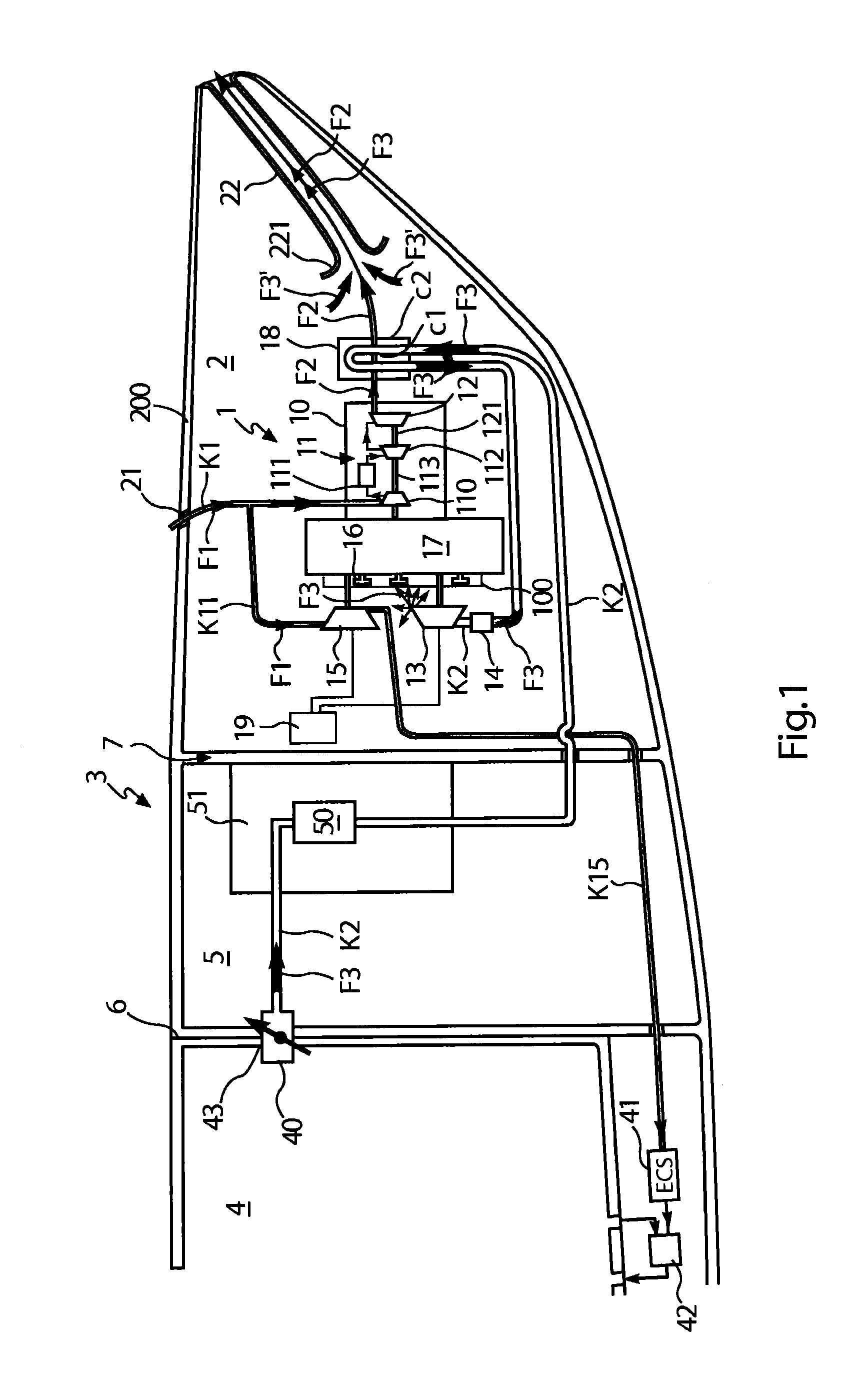
[0049]In reference to FIG. 1 showing a schematic diagram, a main power unit 1 is arranged in an aft compartment 2 situated in the downstream part of the aircraft 3. The passenger cabin 4 is situated upstream and coupled with the aft compartment 2 via an intermediate compartment 5. A pressure bulkhead 6 separates the cabin 4 from the intermediate compartment and a fireproof bulkhead 7 insulates the intermediate compartment 5 from the aft compartment 2, which is fitted with an outside-air intake 21 and an exhaust nozzle 22.

[0050]The main power unit 1 includes an engine 10, of the APU type but of the engine category, combined with an energy-recovery structure. The auxiliary engine consists of: a gas generator or HP body 11, including an intake compressor 110 for an air flow F1 coming from the air intake 21; a combustion chamber 111; and a turbine 112 f...


PUM


Abstract

A method and system limiting specific consumption of an aircraft by matching sizing of a power supply to actual power needs of a cabin pressure control system. The method optimizes overall efficiency of energy supplied onboard an aircraft including, in an environment near the cabin, at least one main power-generating engine, sized to serve as a single pneumatic energy-generating source for the cabin and as an at most partial propulsive, hydraulic, and/or electric energy-generating source for the rest of the aircraft. The method minimizes power differential between a nominal point of the power sources when the sources are operating, and a sizing point of non-propulsive energy contributions of the sources when the main engine has failed, by equally dividing power contributions of the main engines and the main power generator under nominal operating conditions and in an event of failure of a main engine.

Description

TECHNICAL FIELD[0001]The invention relates to a method for optimizing the overall efficiency of the energy supplied aboard an aircraft, this energy being propulsive or non-propulsive, as well as to a main power unit for implementing such a method.[0002]The invention applies to the engine set of aircrafts, i.e. essentially to the engine set of airplanes (jet engines, turbojet engines, turboprops) as well as to the engine set of helicopters (turboshaft engine).[0003]Typically, in an aircraft, the cabin which accommodates the passengers is air-conditioned and / or pressurized. An air inlet of the cabin is connected to an environmental control system ECS (initials for “Environmental Control System”) which adjusts the air-flow rate, temperature and / or pressure in collaboration with a possible recirculating system between the ECS system and the cabin.STATE OF THE ART[0004]It is known how to recover energy between the air at the outlet of the cabin, which has high pressure and temperature—ty...

Claims


Application Information

Patent Timeline
IPC IPC(8): B64D13/06B64D31/00F02C7/32B64D41/00
CPCB64D41/00B64D2013/0611F01D17/165B64D31/00Y02T50/53F05D2220/50B64D13/06F02C7/32Y02T50/50
Inventor HAILLOT, JEAN-MICHEL
Owner SAFRAN HELICOPTER ENGINES
Why Eureka
Try Eureka