Turbofan engine cowl assembly and method of operating the same

a technology of engine cowl and inner core, which is applied in the direction of marine propulsion, vessel construction, aircraft navigation control, etc., can solve problems affecting the efficiency of the fan assembly, and achieve the effect of improving engine efficiency

Active Publication Date: 2008-05-15
GENERAL ELECTRIC CO
View PDF20 Cites 80 Cited by
  • Summary
  • Abstract
  • Description
  • Claims
  • Application Information

AI Technical Summary

Benefits of technology

[0004]In one aspect, a method for operating a turbofan engine assembly is provided. The turbofan engine assembly includes a core gas turbine engine, a core cowl which circumscribes the core gas turbine engine, a nacelle positioned radially outward from the core cowl, a fan nozzle duct defined between the core cowl and the nacelle, and a first core cowl baffle positioned within the fan nozzle duct and a second core cowl baffle wherein a portion of the second core cowl baffle is repositionable with respect to the first core cowl baffle. The method includes varying an operating speed of the fan assembly from a first operating speed to a second operating speed, and selectively positioning a portion of the second core cowl baffle between a first operational position and a second operational position with respect to the first core cowl baffle to vary a throat area of the fan nozzle duct to facilitate improving engine efficiency at the second operating speed.

Problems solved by technology

However, if the engine assembly does not include a thrust reverser assembly, the area of the fan nozzle duct becomes fixed and affects the efficiency of the fan assembly.

Method used


Image

  • Turbofan engine cowl assembly and method of operating the same
  • Turbofan engine cowl assembly and method of operating the same
  • Turbofan engine cowl assembly and method of operating the same

Examples


Embodiment Construction

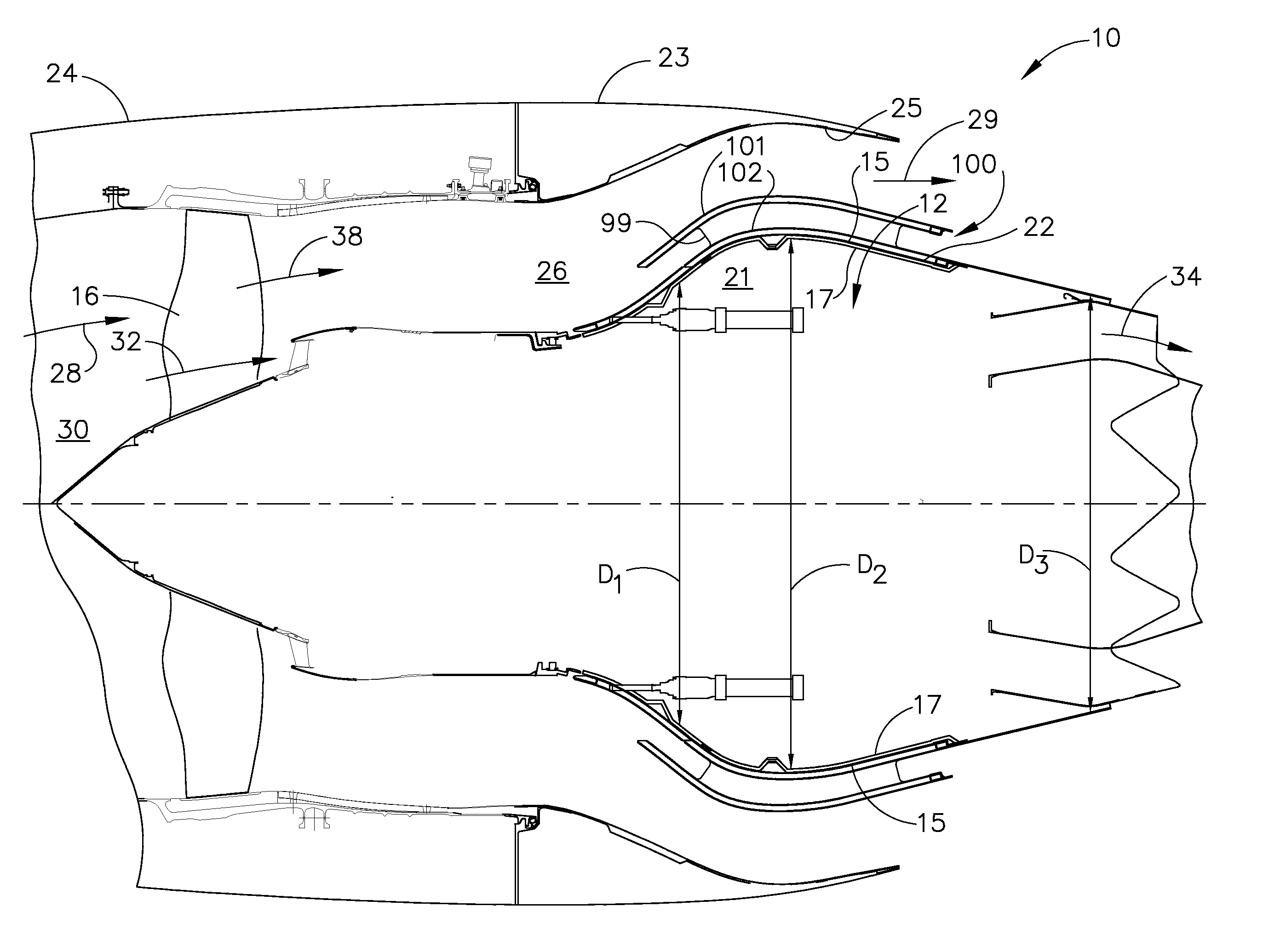
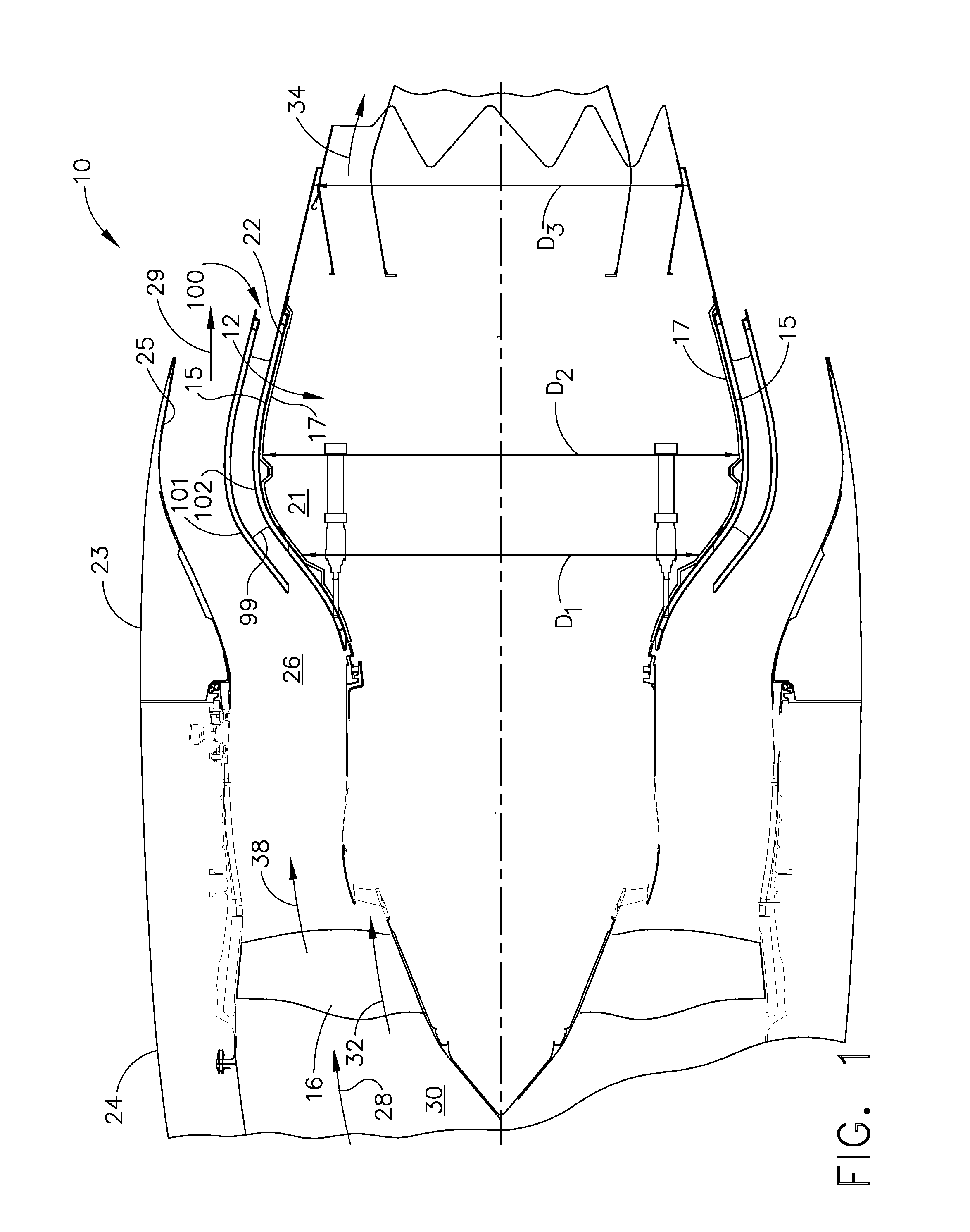
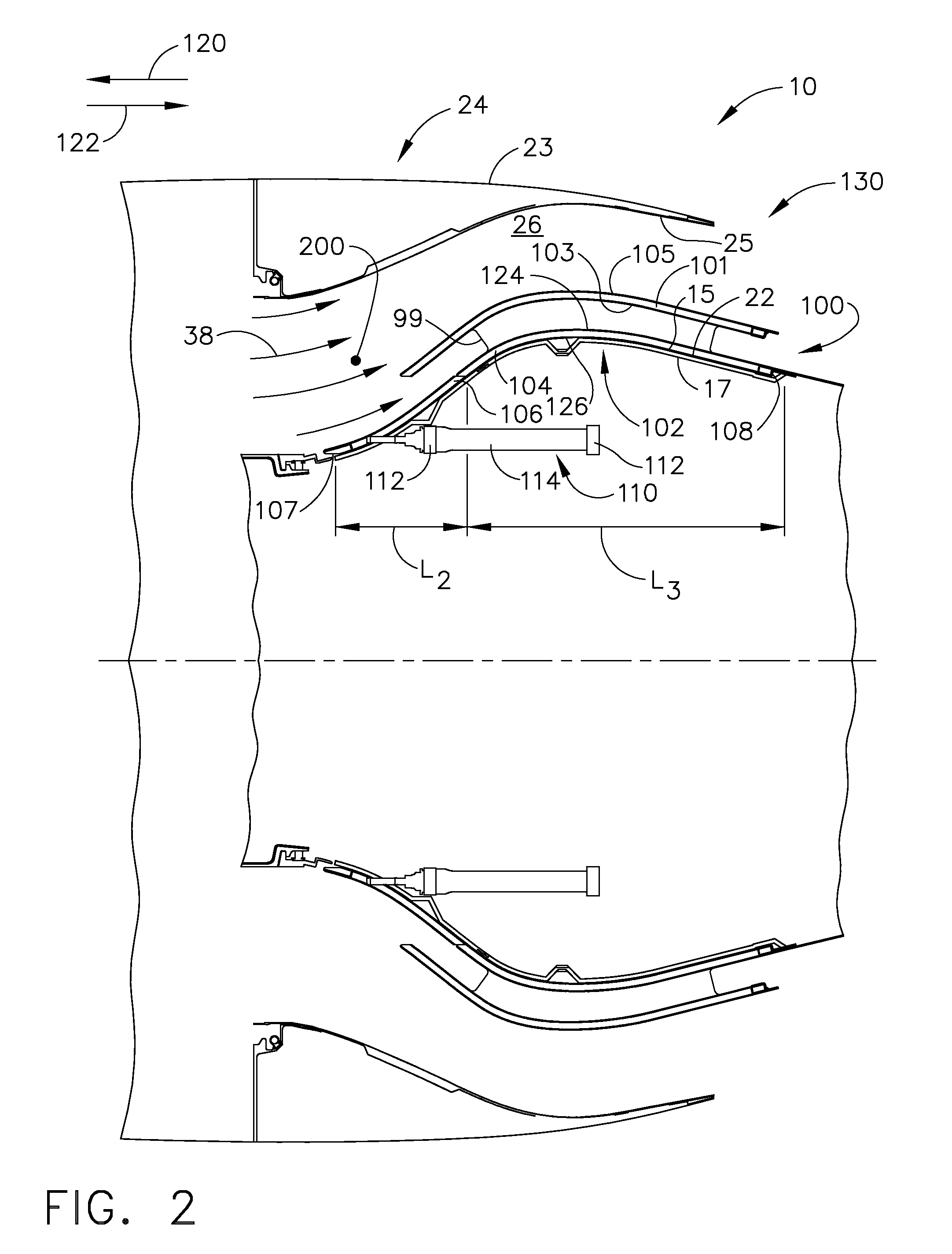
[0010]FIG. 1 is a schematic view of exemplary turbofan engine assembly 10 that includes an inner core cowl baffle assembly 100. FIG. 2 is a partly sectional side view of inner core cowl baffle assembly 100 in a first operational position 130. FIG. 3 is a partly sectional side view of the inner core cowl baffle assembly 100 in a second operational position 132.

[0011]In the exemplary embodiment, turbofan engine assembly 10 includes a core gas turbine engine 20 that includes a high-pressure compressor, a combustor, and a high-pressure turbine (all not shown). Turbofan engine assembly 10 also includes a low-pressure turbine (not shown) that is disposed axially downstream from core gas turbine engine 20, and a fan assembly 16 that is disposed axially upstream from core gas turbine engine 20. In the exemplary embodiment, turbofan engine assembly 10 includes an annular core cowl 22 that extends around core gas turbine engine 20 and includes a radially outer surface 15 and a radially inner ...


PUM


Abstract

A turbofan engine assembly is provided. The turbofan engine assembly includes a core gas turbine engine, a core cowl which circumscribes the core gas turbine engine, a nacelle positioned radially outward from the core cowl, a fan nozzle duct defined between the core cowl and the nacelle, and an inner core cowl baffle assembly positioned within the fan nozzle duct. The inner core cowl baffle assembly includes a first core cowl baffle coupled to a portion of the core cowl within the fan nozzle duct, a second core cowl baffle coupled to a portion of the core cowl and positioned a distance radially inward from the first core cowl baffle, and an actuator assembly configured to vary the throat area of the fan nozzle duct by selectively repositioning the second core cowl baffle with respect to the first core cowl baffle. A method for operating the turbofan engine assembly is also provided.

Description

BACKGROUND OF THE INVENTION[0001]This invention relates generally to turbofan engines, and more particularly to an inner core cowl baffle that may be utilized with a turbofan engine.[0002]At least one known turbofan engine includes a fan assembly, a core gas turbine engine enclosed in an annular core cowl, and a fan nacelle that surrounds a portion of the core gas turbine engine. The fan nacelle is spaced radially outward from the annular core cowl such that the core cowl and fan nacelle form a fan nozzle duct having a discharge area (A18).[0003]At least some known turbofan engines include a thrust reverser assembly. Known thrust reverser assemblies include a first fixed cowl and a second cowl that is axially translatable with respect to the first cowl. Generally, an actuator is coupled to the second cowl to reposition the second cowl with respect to the first cowl. As the second cowl is repositioned, airflow is discharged from the fan nozzle duct through the thrust reverser assembl...

Claims


Application Information

Patent Timeline
Patent Type & Authority Applications(United States)
IPC IPC(8): F01D1/02
CPCF02K1/08F02K3/075F02K3/06F02K1/386F02K1/06
Inventor ORLANDO, ROBERT JOSEPHMONIZ, THOMAS ORYSEDA, JORGE FRANCISCO
Owner GENERAL ELECTRIC CO
Why Eureka
Try Eureka