
Geared counter-rotating gas turbofan engine

a gas turbine engine and counter-rotating technology, applied in combination engines, machines/engines, mechanical equipment, etc., can solve the problems of increasing the demands of gas turbofan engines to reduce system fuel burn, the speed at which the turbine develops power efficiently is not always the same, and the power of the turbine is not always efficien

Active Publication Date: 2011-09-13
RTX CORP
View PDF40 Cites 82 Cited by
  • Summary
  • Abstract
  • Description
  • Claims
  • Application Information

AI Technical Summary

Problems solved by technology

Gas turbofan engines are subject to ever increasing demands to decrease system fuel burn.
There is an inherent mismatch between the speeds at which a turbine develops power efficiently and that of a fan (propulsor) which operates more efficiently at lower speeds.
This results in a relatively shorter and lighter machine.
Disadvantageously, the counter-rotating fan may be relatively complicated and may generate significant acoustic disturbances.

Method used


Image

  • Geared counter-rotating gas turbofan engine
  • Geared counter-rotating gas turbofan engine
  • Geared counter-rotating gas turbofan engine

Examples


Embodiment Construction

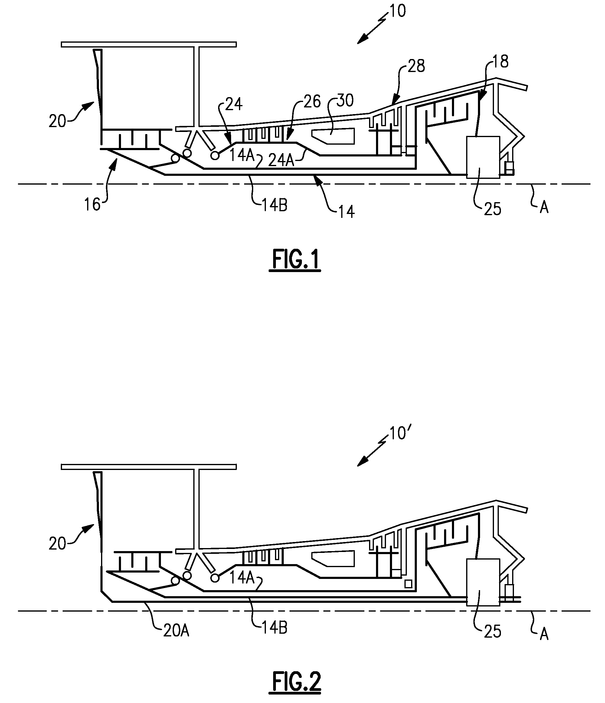
[0010]FIG. 1 illustrates a general schematic view of a gas turbofan engine 10. The turbofan engine 10 includes a low pressure spool 14 and a high pressure spool 24 which rotate about an engine axis of rotation A. The low pressure spool 14 includes a counter-rotating low pressure compressor 16 and a counter rotating low pressure turbine 18 driven by a first low pressure shaft 14A which counter-rotates relative a second low pressure shaft 14B. The high pressure spool 24 includes a high pressure compressor 26 and high pressure turbine 28 mounted to a high pressure shaft 24A for rotation therewith. A combustor 30 is arranged between the high pressure compressor 26 and high pressure turbine 28.

[0011]Core airflow compressed by the counter-rotating low pressure compressor 16 and the high pressure compressor 26 is mixed with the fuel in the combustor 30, ignited, and burned. The resultant high pressure combustor products are expanded through the high pressure turbine 28 and counter rotating...


PUM


Abstract

A gas turbine engine includes a gear system driven by a first and second counter rotating low pressure shaft and a fan driven by the gear system.

Description

BACKGROUND OF THE INVENTION[0001]The present invention relates to a gas turbine engine and more particularly to a gas turbine engine with a fan driven through a geared counter-rotating low pressure spool.[0002]Gas turbofan engines are subject to ever increasing demands to decrease system fuel burn. There is an inherent mismatch between the speeds at which a turbine develops power efficiently and that of a fan (propulsor) which operates more efficiently at lower speeds.[0003]Counter-rotating systems with a counter-rotating rotor that drives a counter-rotating fan may provide efficient operation as every airfoil is involved in compression or power extraction. This results in a relatively shorter and lighter machine. Disadvantageously, the counter-rotating fan may be relatively complicated and may generate significant acoustic disturbances.SUMMARY OF THE INVENTION[0004]A gas turbine engine according to an exemplary aspect of the present invention includes: a first low pressure shaft; a...

Claims


Application Information

Patent Timeline
Patent Type & Authority Patents(United States)
IPC IPC(8): F02K3/00
CPCF02C3/107F02K3/072Y02T50/671F05D2260/40F05D2260/4031F02C3/067Y02T50/60
Inventor NORRIS, JAMES W.MERRY, BRIAN D.
Owner RTX CORP
Learn More