Internally controllable fuel cell

a fuel cell, controllable technology, applied in the direction of electrolysis components, generators/motors, electrochemical generators, etc., can solve the problems of complex protective technology, low availability of fuel cells in use today, and inability to control the dynamics of fuel cells

Active Publication Date: 2014-12-18
HELMUT SCHMIDT UNIV UNIV DER BUNDESWEHR HAMBURG +1
View PDF5 Cites 5 Cited by
  • Summary
  • Abstract
  • Description
  • Claims
  • Application Information

AI Technical Summary

Benefits of technology

[0032]These and other aspects of the present invention will be explained

Problems solved by technology

However, the fuel cells in use today have a relatively low availability which is far below the availability of other energy-producing plants, for example, condensation power plants or wind power plants.
Furthermore, the fuel cells in use today have relatively poor dynamics, in particula

Method used


Image

  • Internally controllable fuel cell
  • Internally controllable fuel cell
  • Internally controllable fuel cell

Examples


Embodiment Construction

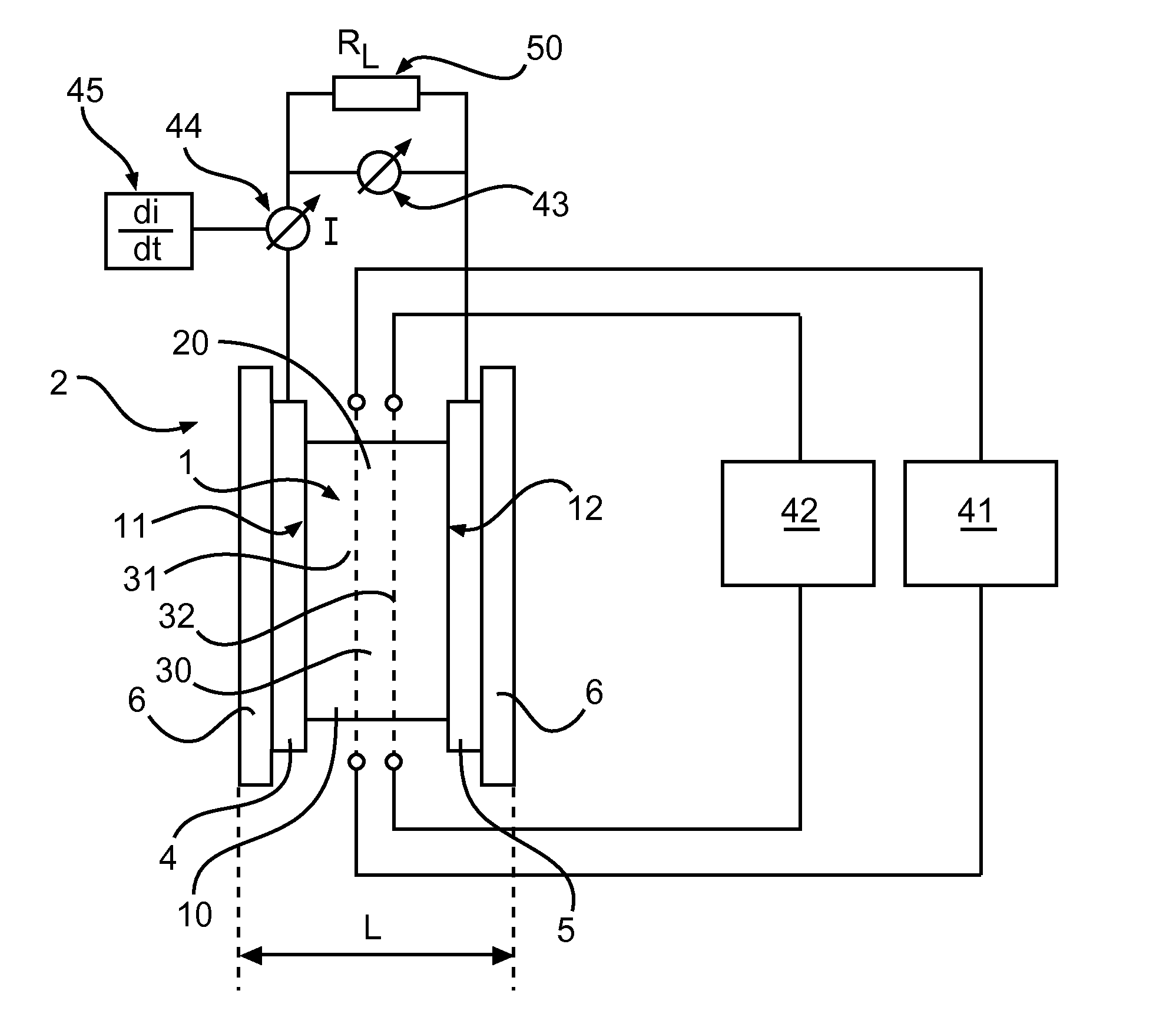
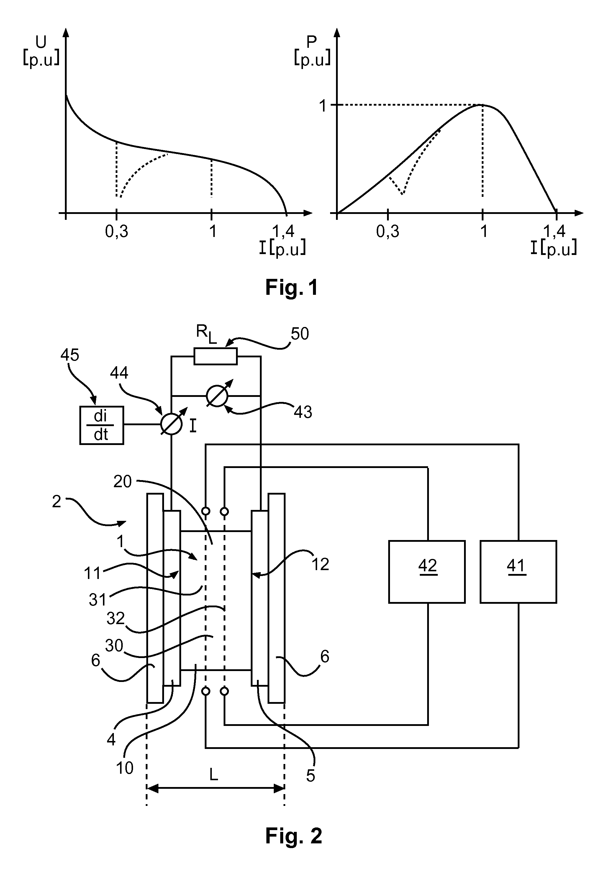
[0045]FIG. 1 shows a typical characteristic line, illustrating the relationship between voltage and current and between power and current in a fuel cell from the prior art. The voltage typically declines as the current increases. The characteristic lines of a fuel cell from the prior art shown in FIG. 1 are curves for the voltage and the current as well as the power, each plotted in a standardized form, i.e., per unit (p.u.). When there is an overload, the characteristic line changes from the curve shown here with a solid line to a curve which is shown according to the dashed line. When there is a heavy load, a voltage drop occurs at a current of 0.3. Likewise when there is a current of 0.3, a drop in performance occurs like that at a high load, e.g., at an overload or a strong dynamic load. These deficiencies at a high overload are addressed by the fuel cell membrane unit and / or fuel cell and high-pressure electrolysis cell according to the invention. FIG. 2 shows a corresponding a...


PUM


Abstract

Fuel cell and/or high-pressure electrolysis cell and a fuel cell membrane arrangement for improved control of a fuel cell by an actuator connected to the fuel cell membrane.

Description

FIELD OF THE INVENTION[0001]The present invention relates to a controllable fuel cell and a controllable high-pressure electrolysis cell and in particular a controllable fuel cell and a high-pressure electrolysis cell with improved dynamics and operating reliability.BACKGROUND OF THE INVENTION[0002]Fuel cells are used to provide an efficient energy supply with a high efficiency. However, the fuel cells in use today have a relatively low availability which is far below the availability of other energy-producing plants, for example, condensation power plants or wind power plants. Furthermore, the fuel cells in use today have relatively poor dynamics, in particular at a high load and / or in the event of a short circuit. Therefore, a complex protective technology must be used for fuel cells. Fuel cells must usually be dimensioned larger to be able to ensure a short-term overload power supply, and therefore they will have a greater weight and a comparatively low power density at the same ...

Claims


Application Information

Patent Timeline
IPC IPC(8): H01M8/04
CPCH01M8/04895H01M8/04291H01M8/04902H01M8/04582H01M8/0271H01M2008/1095C25B13/02C25B13/04H02N2/18Y02E60/36Y02E60/50C25B1/04C25B9/05H01M8/04298H01M8/02H01M8/10C25B1/00
Inventor SCHULZ, DETLEF
Owner HELMUT SCHMIDT UNIV UNIV DER BUNDESWEHR HAMBURG
Why Eureka
Try Eureka