Tire testing method and tire testing machine

a tire testing and tire technology, applied in vehicle testing, structure/machine measurement, ways, etc., can solve the problems of difficult to conduct tire testing with high accuracy, degraded tire quality, and longer cycle time for testing, so as to increase the drum load to the test load, and reduce the test cycle time

Active Publication Date: 2014-12-25
KOBE STEEL LTD
View PDF5 Cites 3 Cited by
  • Summary
  • Abstract
  • Description
  • Claims
  • Application Information

AI Technical Summary

Benefits of technology

[0014]According to the tire testing method and the tire testing machine, right after detecting the contact between the tire and the drum, the rotation of the tire is accelerated from the predetermined rotational speed to the specified rotational speed. In addition, using the time required until the rotational speed of the tire reaches the specified rotational speed from the predetermined rotational speed, the load (drum load) that the drum applies to the tire is increased to th

Problems solved by technology

However, the tire testing machine disclosed in U.S. Pat. No. 6,016,695 has the following problems.
If the rotation of the tire is accelerated to increase the rotational speed to the specified rotational speed in a state of contacting the drum with the stationary tire, and the tire is rapidly accelerated at a time of rotating the tire, then the surface of the tire in contact with the drum is scraped off, a flat spot occurs on the tire, t

Method used


Image

  • Tire testing method and tire testing machine
  • Tire testing method and tire testing machine
  • Tire testing method and tire testing machine

Examples


Embodiment Construction

[0022]Hereinafter, embodiments of tire testing conveyors according to the present invention will be described according to a specific example by referring to the drawings.

[0023]It is to be noted that the embodiments described hereinafter are given only for illustrative purposes and are not intended to indicate applicable limits to a tire testing method and a tire testing machine according to the present invention. That is, the tire testing method and the tire testing machine according to the present invention are not limited to the following embodiments but various changes and modifications can be made of the tire testing method and the tire testing machine according to the present invention without departure of the scope of the claimed invention.

(Configuration of Tire Testing Apparatus)

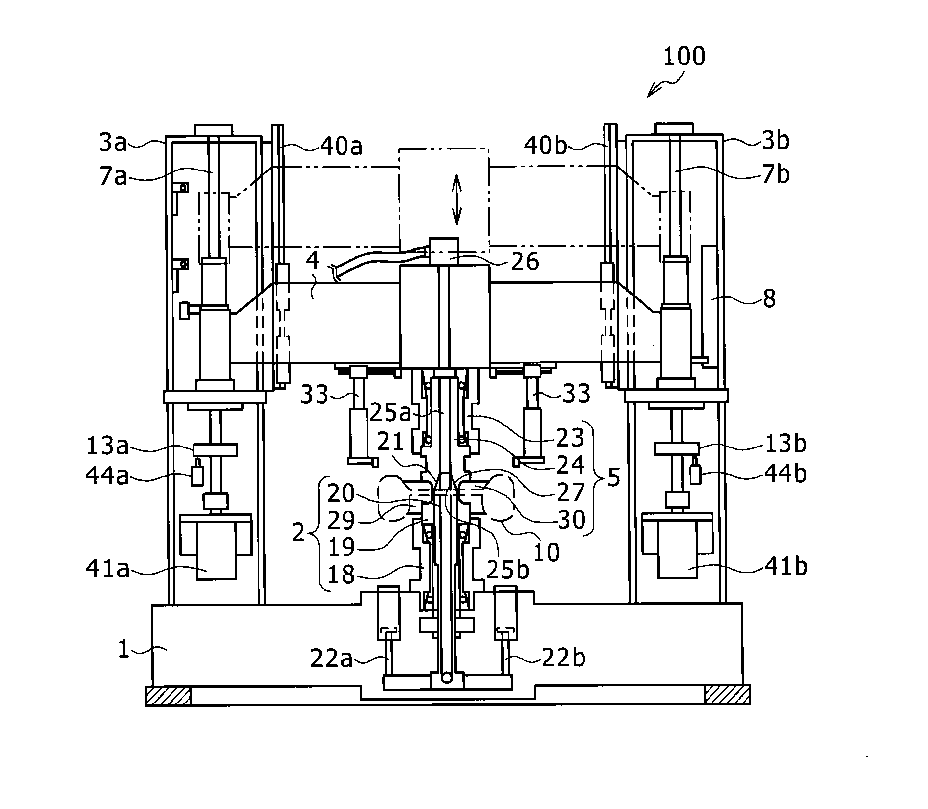
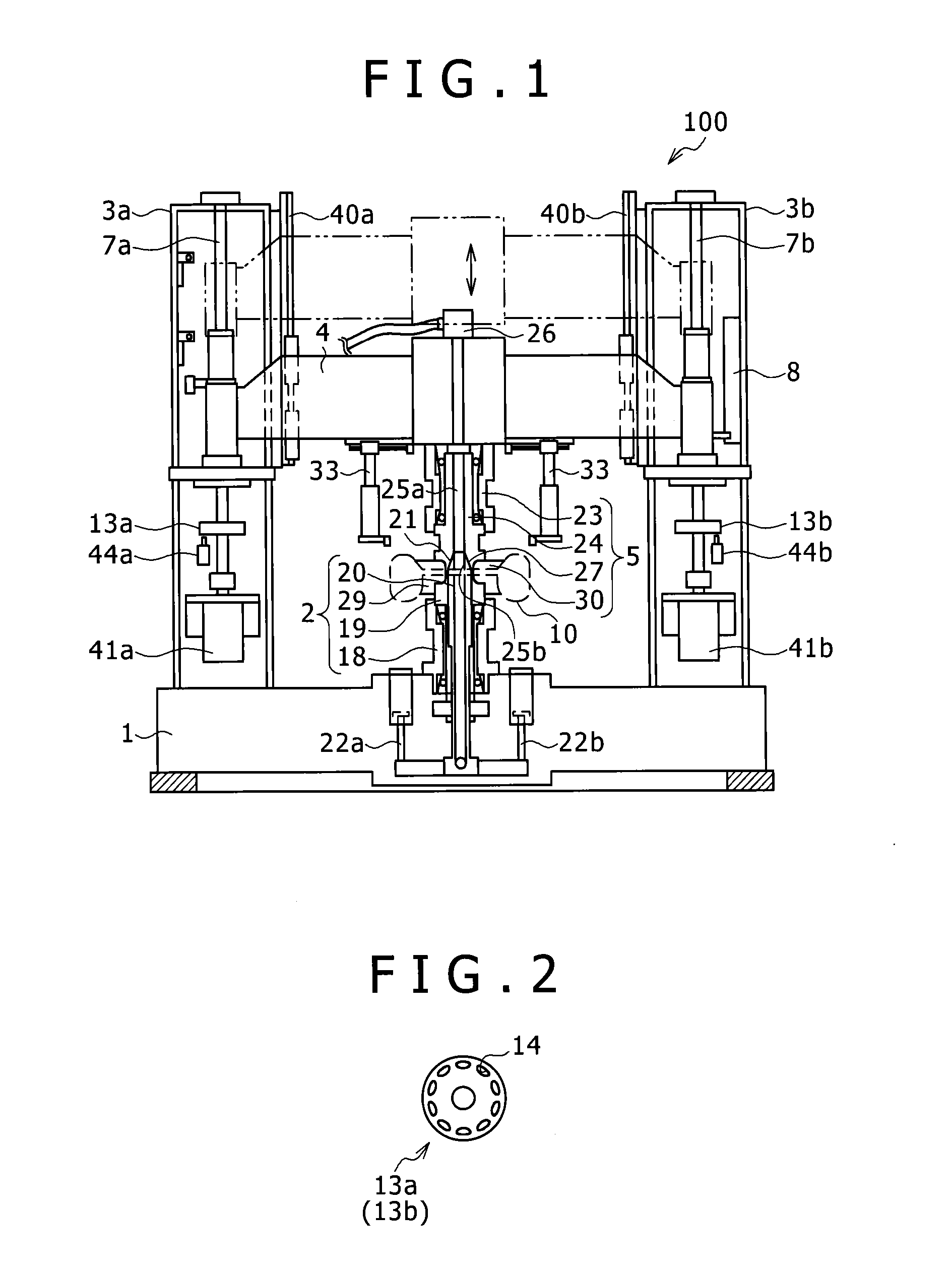
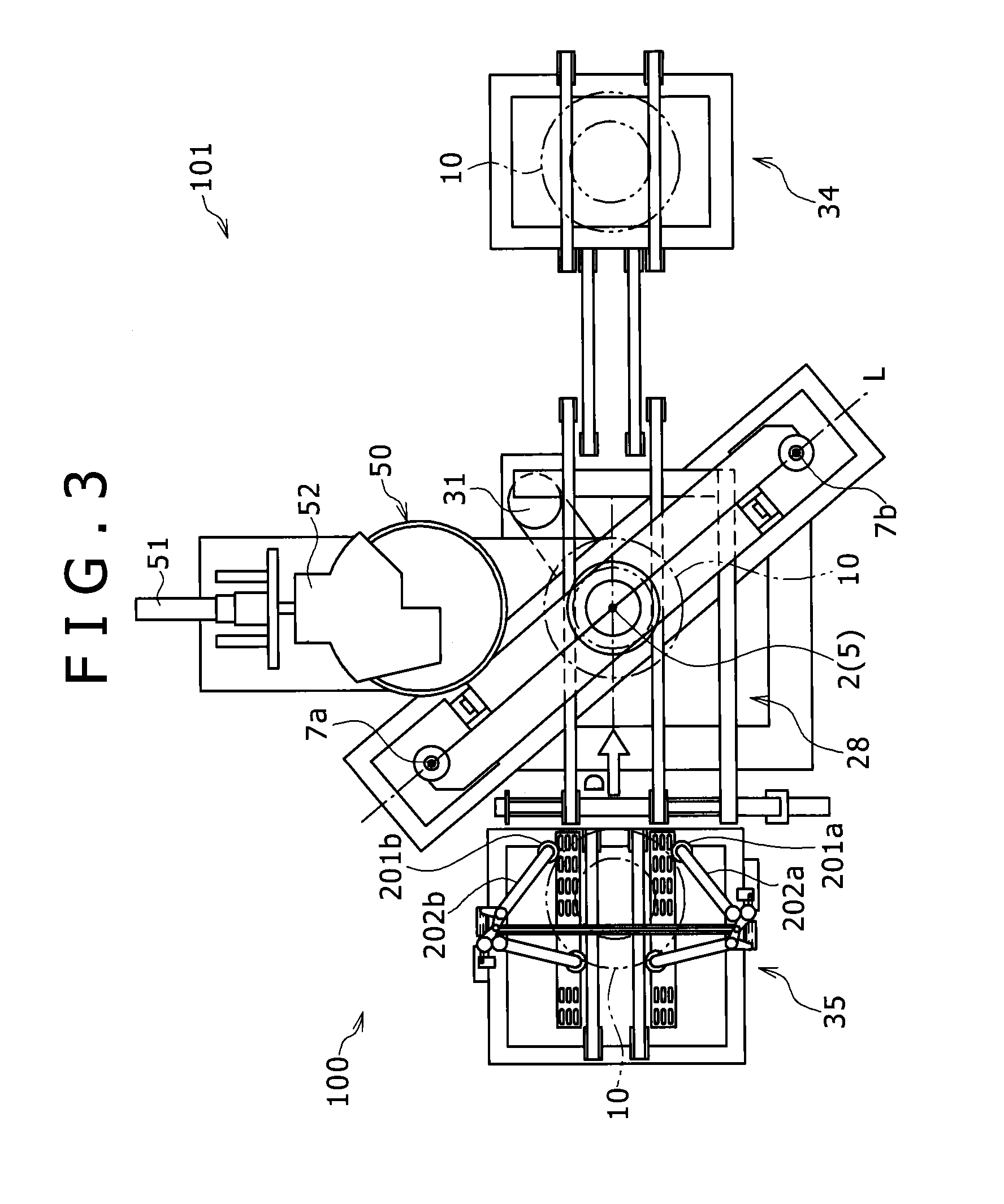
[0024]An overall configuration of a tire testing apparatus 101 including a tire testing machine 100 according to an embodiment of the present invention will be described with reference to FIG. 1.

[002...


PUM


Abstract

To prevent occurrence of a slip between a tire and a drum and a flat spot on the tire and to reduce cycle time at a time of testing the tire, this tire testing method includes causing a control mechanism to control a motor to drive the tire to rotate at a predetermined rotational speed lower than a specified rotational speed if a linear sensor detects that the tire transported onto a center conveyor is sandwiched between an upper spindle and a lower spindle, and to control a moving mechanism to move a drum until the drum contacts the tire that rotates at the predetermined rotational speed. If a load cell detects the contact between the tire and the drum, then the control mechanism accelerates the rotation of the tire from the predetermined rotational speed to the specified rotational speed and increases a load applied to the tire by the drum, and the tire is tested.

Description

BACKGROUND OF THE INVENTION[0001]1. Field of the Invention[0002]The present invention relates to a method for testing a tire and a tire testing machine.[0003]2. Description of the Related Art[0004]Hitherto, a tire mounted on a vehicle or the like often has non-uniform circumferential portions in modulus of elasticity, dimensions, and shapes since the tire is produced by laminating various materials such as rubber, chemical fiber, and steel cord. Reactive forces of components changing periodically depending on road surfaces during high speed rotation and vibrations are generated in such non-uniform portions of the tire, and these cause degradation in traveling performance. These intended uniform performances of the tire are generally referred to as “tire uniformity”. To this end, a circumferential uniformity test is conducted on the tire by a tire testing machine after the tire is subjected to vulcanization molding. This tire testing machine tests the tire with the tire driven to rot...

Claims


Application Information

Patent Timeline
IPC IPC(8): G01M17/02
CPCG01M17/02G01M17/022
Inventor WAKAZONO, TAKEHIKO
Owner KOBE STEEL LTD
Why Eureka
Try Eureka